
4 layers48 × 35 mm

 nmunnich/mini-dongle1
A minimal dongle for use with zmk.
Dongle is an open-source printed circuit board by nmunnich, from the nmunnich/mini-dongle repository on GitHub, published under the Apache-2.0 licence. It is a 2-layer board of 11.3 × 20.7 mm with 29 parts on 73 nets, routed with 237 tracks and 52 vias.
It is built around the USBLC6-2P6. Its parts include 17 capacitors, 3 resistors, 2 ICs, 2 inductors and 1 connector. It belongs with the keyboards and input boards and the nRF52 and nRF5x boards of this library.
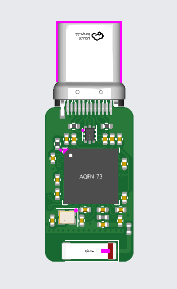
This is an attempt to make as miniature of a dongle for ZMK as is realistically possible. PCB size: 20.66mmx11.3mm
By realistically, I mean to not be completely unaffordable to produce. It could be made smaller through the use of components on both sides and via-in-pad, but this would raise the cost by a large degree. Likewise for reducing the width of traces even further - theoretically sound and wouldn't have any issues with the current levels we are dealing with, but financially unviable.
Despite my best efforts, it turns out to be financially unviable for PCBA -- in large enough quantities it would be fine, but thanks to FCC/CE certification the amount of orders needed would be unrealistic for something like this.
However, it should be perfectly fine for someone who has a hot plate and happens to be ordering parts from a site such as digikey/mouser already. If someone has a reflow oven and wants me to design a version that has components on both sides, let me know.
Note that the PCB antenna trace width to get the correct impedence was calculated using JLCPCB's tool, so I cannot recommend ordering this from anywhere else without first redoing said calculation and adjusting the width appropriately.
Disclaimer: I am not a professional RF engineer, I merely followed the schematics on the datasheets for the components as closely as possible. I am fairly confident that it works, but there is always the chance of an error as it has not been tested.
| Qty | Value | Footprint | References |
|---|---|---|---|
| 5 | 100nF | Capacitor_SMD:C_0402_1005Metric | C5, C7, C8, C12, C31 |
| 3 | 4.7uF | Capacitor_SMD:C_0402_1005Metric | C6, C19, C20 |
| 2 | 0.8pF | Capacitor_SMD:C_0402_1005Metric | C3, C30 |
| 2 | 15pF | Capacitor_SMD:C_0402_1005Metric | C1, C2 |
| 2 | 1uF | Capacitor_SMD:C_0402_1005Metric | C14, C15 |
| 2 | 5.1K | Resistor_SMD:R_0402_1005Metric | R4, R5 |
| 1 | 0.5pF | Capacitor_SMD:C_0402_1005Metric | C4 |
| 1 | 100pF | Capacitor_SMD:C_0402_1005Metric | C11 |
| 1 | 2.2 | Resistor_SMD:R_0402_1005Metric | R1 |
| 1 | 32MHz | Crystal:Crystal_SMD_2016-4Pin_2.0x1.6mm | Y1 |
| 1 | 4.7nH | Inductor_SMD:L_0402_1005Metric | L1 |
| 1 | 5.6nH | Inductor_SMD:L_0402_1005Metric | L3 |
| 1 | 820pF | Capacitor_SMD:C_0402_1005Metric | C9 |
| 1 | Antenna | RF_Antenna:Johanson_2450AT43F0100 | AE1 |
| 1 | SWC | TestPoint:TestPoint_Pad_2.0x2.0mm | TP2 |
| 1 | SWD | TestPoint:TestPoint_Pad_2.0x2.0mm | TP1 |
| 1 | USBLC6-2P6 | Package_TO_SOT_SMD:SOT-666 | U1 |
| 1 | USB_C_Plug_USB2.0 | Connector_USB:USB_C_Plug_Molex_105444 | P1 |
| 1 | nRF52840 | Package_DFN_QFN:Nordic_AQFN-73-1EP_7x7mm_P0.5mm | U2 |
It measures 11.3 × 20.7 mm and has 2 copper layers, 1.6 mm thick.
29 parts, built around the USBLC6-2P6. The full list of its parts is on this page, with links to each part's symbol and footprint where PCBKit's library has them.
From the nmunnich/mini-dongle repository on GitHub, at the commit this page was made from: the board is dongle.kicad_pcb and its schematic dongle.kicad_sch. PCBKit opens the board in the browser, with nothing to install.
Its repository publishes it under the Apache-2.0 licence: you may reuse it on that licence's terms (keep the author's notice, and for a copyleft licence share your changes alike).

Bastardkb/Dilemma
The Dilemma is a vertical stagger low-profile keyboard with mods.


Twisted-Fields/rp2040-motor-controller
A dual channel brushless motor controller based on the RP2040 microcontroller, designed in Kicad.


ZSWatch/Watch-DevKit-HW
The hardware repo for the ZSWatch Development Kit.