2 layers55 × 485 mm
 nmahadevan12/Light-Tracker
Solo dual-axis light tracker on ATmega328P — MOSFET H-bridges, fixed-point Kalman, UART telemetry, 4-layer KiCad PCB.
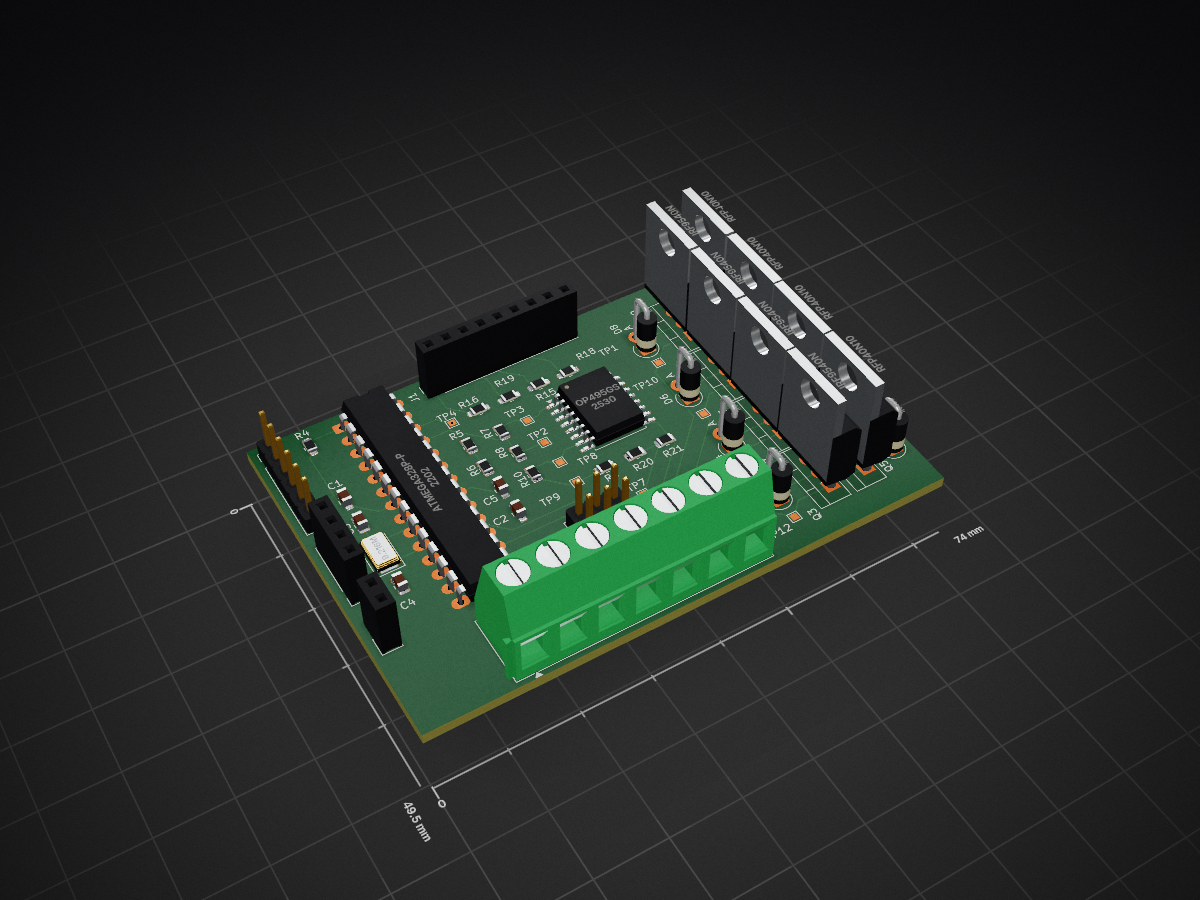
Light tracker dfm is an open-source printed circuit board by nmahadevan12, from the nmahadevan12/Light-Tracker repository on GitHub. It is a 4-layer board of 74 × 49.5 mm with 54 parts on 45 nets, routed with 214 tracks and 25 vias.
It is built around the ATMEGA328P-PU, OP495GSZ and IRF9540NS, with the RFP40N10LE among its other parts. Its parts include 13 resistors, 8 diodes, 8 transistors, 6 connectors and 5 capacitors. It belongs with the interfaces and adapters boards and the AVR (ATmega, ATtiny) boards of this library.


A battery-powered dual-axis light tracker on an ATmega328P. Bare-metal C drives DC motors through MOSFET H-bridges, with LDR sensing, fixed-point Kalman filtering, Hall-effect tilt limits, and UART telemetry to a Python logger.
.
├── ATmega328P Datasheet/
├── Images/
├── Kicad Files/          # Schematics + PCB
├── src/
│   ├── IoT Logging/      # Python UART logger (folder name is historical)
│   └── Source Code/      # AVR C firmware
└── README.mdDesign notes, gallery, and interactive PCB: nmahadevan12.github.io/projects/light-tracker/
| Qty | Value | Footprint | References |
|---|---|---|---|
| 11 | TestPoint | TestPoint:TestPoint_Pad_1.0x1.0mm | TP1, TP2, TP3, TP4, TP5, TP7, TP8, TP9, TP10, TP11, TP12 |
| 8 | 1N4007 | Diode_THT:D_DO-41_SOD81_P2.54mm_Vertical_AnodeUp | D3, D4, D5, D6, D7, D8, D9, D10 |
| 5 | 10k 1% | Resistor_SMD:R_0805_2012Metric | R4, R6, R8, R9, R20 |
| 4 | 1k 1% | Resistor_SMD:R_0805_2012Metric | R15, R16, R18, R19 |
| 4 | 40k 1% | Resistor_SMD:R_0805_2012Metric | R5, R7, R10, R21 |
| 4 | IRF9540N | Package_TO_SOT_THT:TO-220-3_Vertical | Q3, Q4, Q7, Q9 |
| 4 | RFP40N10 | Package_TO_SOT_THT:TO-220-3_Vertical | Q5, Q6, Q8, Q10 |
| 3 | 100n 1% | Capacitor_SMD:C_0805_2012Metric | C1, C2, C5 |
| 2 | 12p 1% | Capacitor_SMD:C_0805_2012Metric | C3, C4 |
| 1 | 9.216M | Crystal:Crystal_SMD_5032-2Pin_5.0x3.2mm | Y1 |
| 1 | ATmega328P-P | Package_DIP:DIP-28_W7.62mm_LongPads | U1 |
| 1 | BATTERIES + MOTOR OUTPUTS | TerminalBlock_Phoenix:TerminalBlock_Phoenix_MKDS-1,5-7-5.08_1x07_P5.08mm_Horizontal | J3 |
| 1 | CAPACITIVE SENSOR | Connector_PinSocket_2.54mm:PinSocket_1x02_P2.54mm_Vertical | J7 |
| 1 | FTDI CABLE | Connector_PinHeader_2.54mm:PinHeader_1x06_P2.54mm_Vertical | J6 |
| 1 | HALL SCREW TERMINAL | Connector_PinSocket_2.54mm:PinSocket_1x04_P2.54mm_Vertical | J2 |
| 1 | ISP | Connector_PinHeader_2.54mm:PinHeader_2x03_P2.54mm_Vertical | J8 |
| 1 | LDR + POT | Connector_PinSocket_2.54mm:PinSocket_1x09_P2.54mm_Vertical | J1 |
| 1 | OP495GS | Package_SO:SOIC-16W_7.5x10.3mm_P1.27mm | U3 |
It measures 74 × 49.5 mm and has 4 copper layers, 1.6 mm thick.
54 parts, built around the ATMEGA328P-PU, OP495GSZ, IRF9540NS and RFP40N10LE. The full list of its parts is on this page, with links to each part's symbol and footprint where PCBKit's library has them.
From the nmahadevan12/Light-Tracker repository on GitHub, at the commit this page was made from: the board is Kicad Files/light tracker dfm/light tracker dfm.kicad_pcb and its schematic Kicad Files/light tracker dfm/cp6-raw_Sensor/cp6-raw_Sensor.kicad_sch. PCBKit opens the board in the browser, with nothing to install.
Its repository states no licence, so its author keeps all rights: ask nmahadevan12 before reusing the design.

profdc9/DRSSTC-PCB-Pack
A pack of PCBs for a dual resonant solid state tesla coil setup. Pretty much everything you need.


kholia/HF-PA-v6
RF "Lego" blocks. Quite-Linear HF broadband RF amplifier experiments for higher bands.

ceteras/PicoLVDS
Tested with B089AW01-V.0 and HSD089IFW1-A00-V1.0 on a breadboard. I'm sure it will work with other displays from old netbooks.

gfoot/fastpdip6502
Fast PDIP-only 6502-based homebrew computer - code and hardware design sources

gfoot/powercontrolcircuit
A soft power supply circuit with tunable overcurrent cutoff
