Skip to the content
2 layers50.8 × 38.1 mmPowercontrol, the printed circuit board in 3D

A soft power supply circuit with tunable overcurrent cutoff

Size
50.8 × 38.1 mm
Copper layers
2
Thickness
1.6 mm
Parts
19
Nets
17
Pads
54
Tracks, vias
79, 27
Routed
Yes
KiCad
KiCad 5 (file 20171130)
Created
21 Mar 2021
Updated
4 Oct 2022

Overview

Powercontrol is an open-source printed circuit board by gfoot, from the gfoot/powercontrolcircuit repository on GitHub, published under the Unlicense licence. It is a 2-layer board of 50.8 × 38.1 mm with 19 parts on 17 nets, routed with 79 tracks and 27 vias.

It is built around the TL072 and IRF9540NS. Its parts include 8 resistors, 3 transistors, 2 switches, 1 capacitor and 1 IC.

Main components

2

README

README.md

Soft Power Switch Circuit with Tunable Overcurrent Protection Cutoff
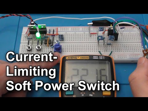
Demo video on YouTube
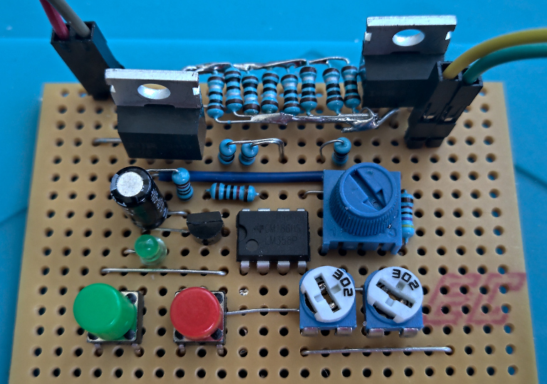
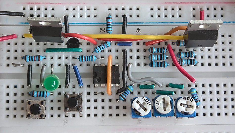
Assembled on breadboardAssembled on veroboardDemo video

This is a circuit for soft-switching a 5V DC input, with a configurable current limit cutoff, tested from around 10mA up to 1.2A.

This is useful because it protects your power supply, wiring, and components against adverse effects due to things like short circuiting, accidental reversed power polarity, placing components incorrectly or backwards in a circuit, or other component failure.

It's not a boost/buck converter or regulator, just a switch for an existing regulated DC input.

Operation

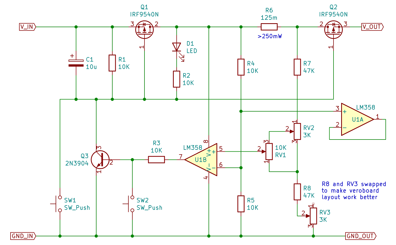
Press SW1 to turn the power on. The LED indicates that power is on. Press SW2 to turn the power off.

Use RV2 and RV3 to tune the range of currents that are selectable. See configuration guide for the tuning procedure.

Once tuned, RV1 selects the current limit. When more than this amount of current is drawn, the circuit automatically powers off.

Schematic
Bill of Materials

RefQtySpecNotes
Q1-22IRF9540NP-channel power MOSFET - ideally low RDS(on) at VGS=-4.25V
Q312N3904NPN BJT transistor
R1-5510KResistor
R61~0.1 ohmPower resistor, 1A continuous current, at least 1W recommended
R7-8247KResistor
RV1-223KTrim pots
RV3110KPotentiometer
U11LM385Operational amplifier
C1110uCapacitor to prevent accidental power-on (may not be necessary)

Exact component choices are not critical. With the above components, and 6x1ohm 250mW resistors in parallel for R6, at a continuous 1A load, the resistors get slightly warm to the touch and the MOSFET tabs measure 60C-70C, in open air with no heatsinks or active cooling.

The added output impedance appears to be approximately 0.75 ohms with these components, at a load current of 1A; lower currents lead to lower impedance. Choosing Q1-2 with lower RDS(on) at -4.25V or more will have the greatest effect on impedance.

Improvements

I'm considering the following:

  • Use a charge pump to lower the gate voltage to Q1-2, to improve impedance at high loads
  • Configure the op amp with feedback to amplify the voltage difference, in case it makes tuning the cutoff simpler
  • Add an optional linear regulator to guarantee output voltage at high loads

Other suggestions very welcome!

Parts

19
QtyValueFootprintReferences
210KResistor_THT:R_Axial_DIN0204_L3.6mm_D1.6mm_P7.62mm_HorizontalR3, R5
210KResistor_THT:R_Axial_DIN0204_L3.6mm_D1.6mm_P5.08mm_VerticalR1, R4
23KPotentiometer_THT:Potentiometer_Runtron_RM-065_VerticalRV2, RV3
2IRF9540NPackage_TO_SOT_THT:TO-220-3_VerticalQ1, Q2
2SW_PushButton_Switch_THT:SW_PUSH_6mm_H5mmSW1, SW2
110KPotentiometer_THT:Potentiometer_Vishay_T73YP_VerticalRV1
110KResistor_THT:R_Axial_DIN0204_L3.6mm_D1.6mm_P2.54mm_VerticalR2
110uCapacitor_THT:CP_Radial_D5.0mm_P2.50mmC1
1167mResistor_THT:R_Axial_Power_L20.0mm_W6.4mm_P25.40mmR6
12N3904Package_TO_SOT_THT:TO-92_Inline_WideQ3
147KResistor_THT:R_Axial_DIN0204_L3.6mm_D1.6mm_P2.54mm_VerticalR8
147KResistor_THT:R_Axial_DIN0204_L3.6mm_D1.6mm_P7.62mm_HorizontalR7
1LEDLED_THT:LED_D3.0mmD1
1TL072Package_DIP:DIP-8_W7.62mmU1

Similar boards

  • 4 layers200 × 142.3 mmFRED Electrical Scheme KiCAD, the printed circuit board in 3D

    FRED Electrical Scheme KiCAD

    GiulianoAgostini04/FRED-Project

    Real-time concentration monitoring system based on frontal-lobe EEG signals. Features a custom PCB designed with TinkerCAD and KiCad, OpenBCI Ganglion and Arduino UNO for signal acquisition, display, and frequency-band…

    93 parts1MIT
  • 2 layers21.7 × 10 mmSensor Unit, the printed circuit board in 3D

    Sensor Unit

    Dooganar/engg3800-t3-eaar-pcb-design

    A repo used to track and collaborate on the pcb design for the University of Queensland "Team Project II" course.

    164 parts
  • 2 layers90.2 × 44.4 mmEnergieplatine, the printed circuit board in 3D

    Energieplatine

    entwickler-brandenburg/Tutorprojekt_Energieplatine

    41 parts
  • 2 layersSoftPower breakout, the printed circuit board in 3D

    SoftPower breakout

    dbuchwald/kicad-simple

    Simple designs in KiCAD that do not require separate projects

    21 parts10MIT
  • 2 layers96.8 × 97 mmPsoc5power, the printed circuit board in 3D

    Psoc5power

    profdc9/DRSSTC-PCB-Pack

    A pack of PCBs for a dual resonant solid state tesla coil setup. Pretty much everything you need.

    133 parts59
  • 2 layersCastVolumeKnob, the printed circuit board in 3D

    CastVolumeKnob

    WebmasterTD/CastVolumeKnob

    Hardware Volume Knob for Google Cast devices

    18 parts25
  • 2 layers102 × 72 mmHF PA Combined, the printed circuit board in 3D

    HF PA Combined

    kholia/HF-PA-v6

    RF "Lego" blocks. Quite-Linear HF broadband RF amplifier experiments for higher bands.

    40 parts11
  • 4 layers98.5 × 82 mmPico2lvds, the printed circuit board in 3D

    Pico2lvds

    ceteras/PicoLVDS

    Tested with B089AW01-V.0 and HSD089IFW1-A00-V1.0 on a breadboard. I'm sure it will work with other displays from old netbooks.

    43 parts7GPL-3.0

Questions

How big is the Powercontrol PCB?

It measures 50.8 × 38.1 mm and has 2 copper layers, 1.6 mm thick.

What parts does the Powercontrol use?

19 parts, built around the TL072 and IRF9540NS. The full list of its parts is on this page, with links to each part's symbol and footprint where PCBKit's library has them.

Where can I download the Powercontrol KiCad files?

From the gfoot/powercontrolcircuit repository on GitHub, at the commit this page was made from: the board is hardware/powercontrol.kicad_pcb. PCBKit opens the board in the browser, with nothing to install.

Can I use the Powercontrol design in my own project?

Its repository publishes it under the Unlicense licence: you may reuse it on that licence's terms (keep the author's notice, and for a copyleft licence share your changes alike).