
4 layers234 × 84 mm
Main panel
google/mozc-devices
Circuit diagrams and firmware source code for Gboard DIY keyboards
234 parts3kApache-2.0
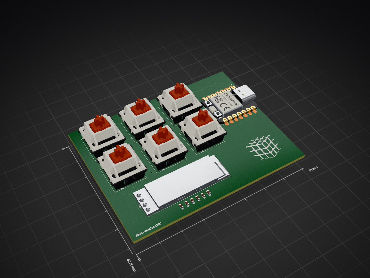
 Nithish1201-code/Hackpad-Shortpad1
A six key macropad with the xiao rp2040, oled displays, per key rgb, and a custom pcb and enclosure i made.
Initial project is an open-source printed circuit board by Nithish1201-code, from the Nithish1201-code/Hackpad-Shortpad repository on GitHub. It is a 2-layer board of 81 × 62.5 mm with 21 parts on 20 nets, routed with 263 tracks and 13 vias.
It is built around the SK6812MINI-E. Its parts include 6 capacitors, 6 diodes, 6 switches and 2 ICs. It belongs with the lEDs and displays and keyboards and input boards of this library.
6-key macropad with an OLED display and RGB LEDs built around a Seeed XIAO RP2040. I made this for Hack Club Stardance because I wanted to build my first proper PCB and get some hands-on experience with electronics, CAD, firmware, and basically the whole process of making a hardware project. I also wanted to earn some Stardust, so getting to learn all of this while working toward something useful felt like a pretty good opportunity.
ShortPad is my first proper hardware project, and pretty much my first time working with most of the tools involved in building something like this. I designed the PCB in KiCad, made a custom two-piece case in Tinkercad, set up QMK firmware, and added an I2C OLED and addressable RGB LEDs to the basic 6-key macropad design.
The main goal was honestly just to get a feel for the whole process. Before starting this, I had never designed a PCB, made a proper 3D case, or worked with QMK, or anything hardware for that matter. So a lot of the project was learning as I went, figuring things out when they didn't work, and gradually putting all the pieces together.
| Component | Quantity | Specification |
|---|---|---|
| Seeed XIAO RP2040 | 1 | XIAO RP2040 |
| OLED Display | 1 | ER-OLEDM0.91 0.91" I2C OLED |
| Mechanical Switches | 6 | Cherry MX-compatible |
| Addressable LEDs | 6 | SK6812MINI-E |
| Capacitors | 6 | 100nF, 0603 SMD |
| Component | Quantity | Specification |
|---|---|---|
| Keycaps | 6 | MX-compatible DSA keycaps |
| Heat-set Inserts | 4 | M3 × 5 × 4 mm |
| Screws | 4 | M3 × 16 mm |
| 3D-printed Case | 1 | Custom case split into top and bottom pieces |
The PCB was designed in KiCad, and this was my first time doing a proper PCB from scratch. The board is built around the XIAO RP2040 and includes the six mechanical switches, six SK6812MINI-E RGB LEDs, the OLED interface, and the supporting components needed for the design.
I wanted to keep the board fairly compact while still making sure everything would fit properly inside the case. I also added a 100nF capacitor for each RGB LED and prepared the Gerber files for manufacturing.
The case was designed from scratch in Tinkercad and is split into separate top and bottom pieces. It uses four M3 heat-set inserts and four M3 × 16 mm screws to hold everything together.
I haven't printed the case yet since the project is currently at the design and approval stage but the final STL files are already included in the repository and are ready for printing.
Built using QMK. The firmware source is in Firmware/hackpad_6key/, and the compiled .uf2 file is included in production/firmware.uf2.
I'm still fairly new to QMK and haven't gone especially deep into it yet. I used AI to help generate part of the initial firmware since there were some areas I wasn't familiar with, then made my own changes and adjustments to get it working the way I wanted.
I also enabled VIA so the macropad can be configured through software instead of having everything permanently hardcoded. And im currently working on the OLED software as well, with the idea that the display and RGB effects can be configured and expanded over time.
This project ended up being a pretty good crash course in hardware development. I learned, or am still learning, things like:
| Area |
|---|
| KiCad and PCB design |
| PCB routing |
| electronics and component selection |
| QMK and VIA |
| I2C and OLED displays |
| addressable RGB LEDs |
| CAD and 3D modelling |
| Tinkercad |
| 3D printing |
| Gerber and other production files |
| designing around a microcontroller and making the different parts of a project work together |
I'm definitely not an expert in all of these yet, especially QMK and complited stuff like that, but that was kinda the point. I wanted to actually build something instead of waiting until I knew everything first, and this gave me a reason to learn a lot of new things along the way.
I wanted to make my first proper PCB, and a macropad seemed like a good project to start with because it was small enough to be manageable but still involved a lot of different parts of hardware development.
It also gave me an excuse to try things I hadn't worked with before like PCB design, CAD, electronics, firmware, OLEDs, RGB LEDs, and eventually 3D printing. And honestly getting some Stardust out of it was another reason I wanted to give it a shot. I'm also interested in getting some basic tools for future projects, like a soldering iron, so being able to build something I actually wanted while also getting resources to keep experimenting felt like a pretty good win-win.
I started Stardance only a couple of days ago, and this project was basically me wanting to see what I could make from scratch. It was my first PCB, my first real CAD project, and my first time bringing all these different parts together into one design. I mainly wanted to get a feel for the process, learn how everything fits together, and hopefully use what I learned here for more ambitious projects later.
| Path | Contents |
|---|---|
CAD/ | Fully assembled.stp |
Firmware/hackpad_6key/ | QMK firmware project |
Firmware/hackpad_6key/keymaps/default/ | Default keymap |
Firmware/hackpad_6key/keymaps/via/ | VIA keymap |
Firmware/hackpad_6key/keymaps/via/keymap.c | VIA keymap source |
Firmware/hackpad_6key/keyboard.json | QMK keyboard definition |
PCB/ | KiCad PCB, project, and schematic files |
production/ | STL files, compiled firmware, and Gerbers |
.gitattributes | Git attributes |
.gitignore | Git ignore rules |
README.md | Project documentation |
The PCB, schematic, CAD model, firmware build, STL files, and Gerber production files are all finished and pushed to the repository. The physical PCB and case haven't been produced yet, so the next step is getting the project approved and then actually making it IRL.
| Qty | Value | Footprint | References |
|---|---|---|---|
| 6 | 100n | Capacitor_SMD:C_0603_1608Metric_Pad1.08x0.95mm_HandSolder | C2, C3, C4, C5, C6, C7 |
| 6 | SK6812MINI-E | kicad-keyboard-parts.pretty-master:MX_SK6812MINI-E | D1, D2, D3, D4, D5, D6 |
| 5 | SW_Push | PCM_Switch_Keyboard_Cherry_MX:SW_Cherry_MX_PCB_1.00u | SW1, SW3, SW4, SW5, SW6 |
| 1 | ER_OLEDM0.91_1x-I2C | Display:ER_OLEDM0.91_1x-I2C | U2 |
| 1 | LOGO | Downloads:silk2 | G*** |
| 1 | MOUDLE-SEEEDUINO-XIAO | footprints:XIAO-Generic-Hybrid-14P-2.54-21X17.8MM | U1 |
| 1 | SW_Push | PCM_Switch_Keyboard_Cherry_MX:SW_Cherry_MX_PCB | SW2 |
It measures 81 × 62.5 mm and has 2 copper layers, 1.6 mm thick.
21 parts, built around the SK6812MINI-E. The full list of its parts is on this page, with links to each part's symbol and footprint where PCBKit's library has them.
From the Nithish1201-code/Hackpad-Shortpad repository on GitHub, at the commit this page was made from: the board is PCB/initial project.kicad_pcb and its schematic PCB/initial project.kicad_sch. PCBKit opens the board in the browser, with nothing to install.
Its repository states no licence, so its author keeps all rights: ask Nithish1201-code before reusing the design.
google/mozc-devices
Circuit diagrams and firmware source code for Gboard DIY keyboards

Bastardkb/Dilemma
The Dilemma is a vertical stagger low-profile keyboard with mods.

Pwnsat/FlatSat
Flatsat v1.0 is a hardware based platform for aerospace cybersecurity research

adamws/kicad-kbplacer
KiCad plugin for automatic keyboard's key placement and routing

imchipwood/dumbpad
Simple 4x4 numpad with rotary encoder. Powered by QMK via ATmega32u4 Pro Micro

makerforgetech/modular-biped
An open source framework for creating a bipedal modular companion robot.

