

2 layers

 ngyuheng/digital-clock
This hardware project is a simple digital clock built using an Arduino Nano, a TM1637 4-digit 7-segment display, and a DS3231 real-time clock (RTC) module.
Digital clock is an open-source printed circuit board by ngyuheng, from the ngyuheng/digital-clock repository on GitHub. It is a 2-layer board of 60 × 48 mm with 8 parts on 32 nets, routed with 43 tracks and 0 vias.
It is built around the TM1637 and DS3231S#. Its parts include 2 resistors and 2 connectors. It belongs with the lEDs and displays boards and the AVR (ATmega, ATtiny) boards of this library.
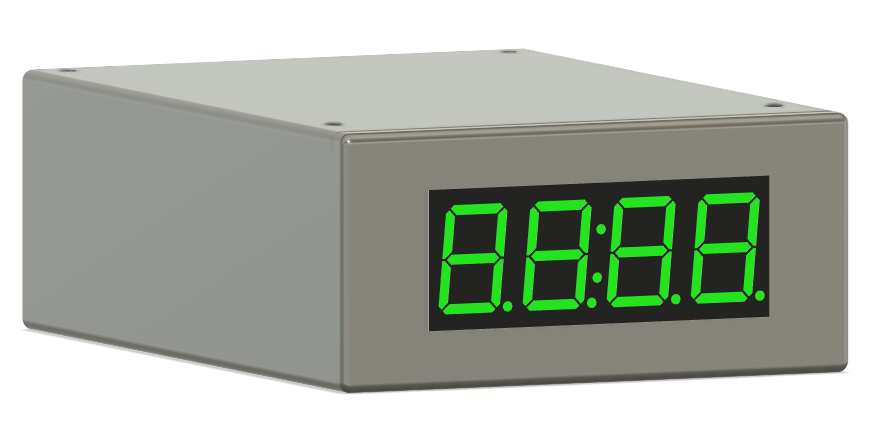
This hardware project is a simple digital clock built using an Arduino Nano, a TM1637 4-digit 7-segment display, and a DS3231 real-time clock (RTC) module.
I wanted to start off with a simple project to practice and learn CADding and PCB designing. This project is relatively simple with only a few components, so it was a good opportunity for me to build something with Hackclub.
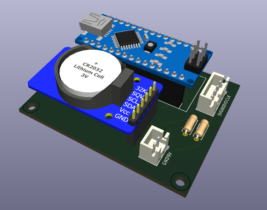
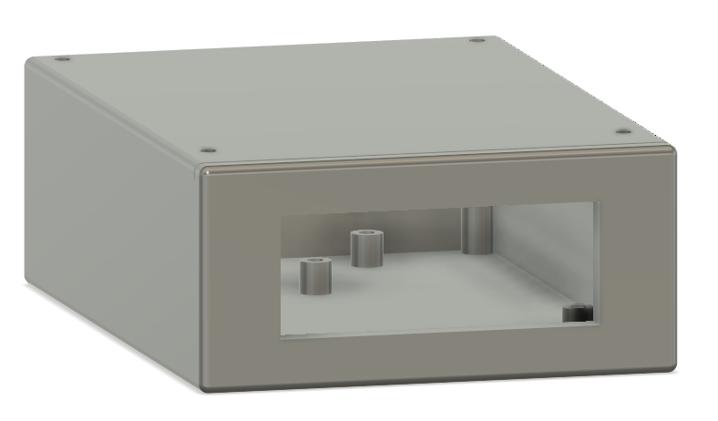
Connect the TM1637 and 9V battery holder to the Arduino Nano by connecting the JST connectors to their corresponding pins.
| Qty | Value | Footprint | References |
|---|---|---|---|
| 2 | R | Resistor_THT:R_Axial_DIN0207_L6.3mm_D2.5mm_P7.62mm_Horizontal | R1, R2 |
| 1 | Arduino_Nano_v3.x | Module:Arduino_Nano | A1 |
| 1 | Battery_Cell | Connector_JST:JST_XH_B2B-XH-A_1x02_P2.50mm_Vertical | BT1 |
| 1 | DS3231 | ds3231:DS3231 | J1 |
| 1 | TM1637 | Connector_JST:JST_XH_B4B-XH-A_1x04_P2.50mm_Vertical | J2 |
The 6 most common of 8 parts.
It measures 60 × 48 mm and has 2 copper layers, 1.6 mm thick.
8 parts, built around the TM1637 and DS3231S#. The full list of its parts is on this page, with links to each part's symbol and footprint where PCBKit's library has them.
From the ngyuheng/digital-clock repository on GitHub, at the commit this page was made from: the board is PCB/digital clock.kicad_pcb and its schematic PCB/digital clock.kicad_sch. PCBKit opens the board in the browser, with nothing to install.
Its repository states no licence, so its author keeps all rights: ask ngyuheng before reusing the design.

keeos-io/ogham
Ogham — a dual-voice bytebeat synthesizer for Eurorack. Firmware (MIT) and hardware (CC BY-SA 4.0).


bitsandpixels-io/kids-control-panel
Spaceship-like control panel for kids, based on Arduino

fehlfarbe/ESP32-Alarm-clock
This is an ESP32 based alarm clock that plays mp3 files from SD, webstreams or even FM radio. You can configure multiple alarms and add new songs to your sd card with a simple webinterface.

galopago/panel-mount-7-segment-display
Open source 7 segment serially controlled led display that fits inside a generic 45x26mm panel mount plastic enclosure. Upgrade your function specific panel meter PCB with a new one controllable by your preferred MCU.

pmalessa/homegreen-Node
The system is based on an inexpensive node, which is able to control up to 3 pumps and can be powered by nearly any conventional powerbank.
