2 layers123 × 87.5 mm
FastLOGIC
Neumi/fastLOGIC
An affordable Arduino-based board designed for straightforward (industrial) logic control, ideal for building small-scale automation and control solutions.
180 parts23MIT

 Neumi/fastLOGIC23
An affordable Arduino-based board designed for straightforward (industrial) logic control, ideal for building small-scale automation and control solutions. FastLOGIC! is designed to cater to the automation needs of various small applications.
FastLOGIC is an open-source printed circuit board by Neumi, from the Neumi/fastLOGIC repository on GitHub, published under the MIT licence. It is a 2-layer board of 60 × 92 mm with 83 parts on 96 nets, routed with 638 tracks and 268 vias.
It is built around the ATMEGA328P-AU, TM1637 and DS18B20, with the EL817, MMBT5551L and R1M among its other parts. Its parts include 26 resistors, 16 capacitors, 13 connectors, 9 diodes and 7 ICs. It belongs with the AVR (ATmega, ATtiny) boards of this library.


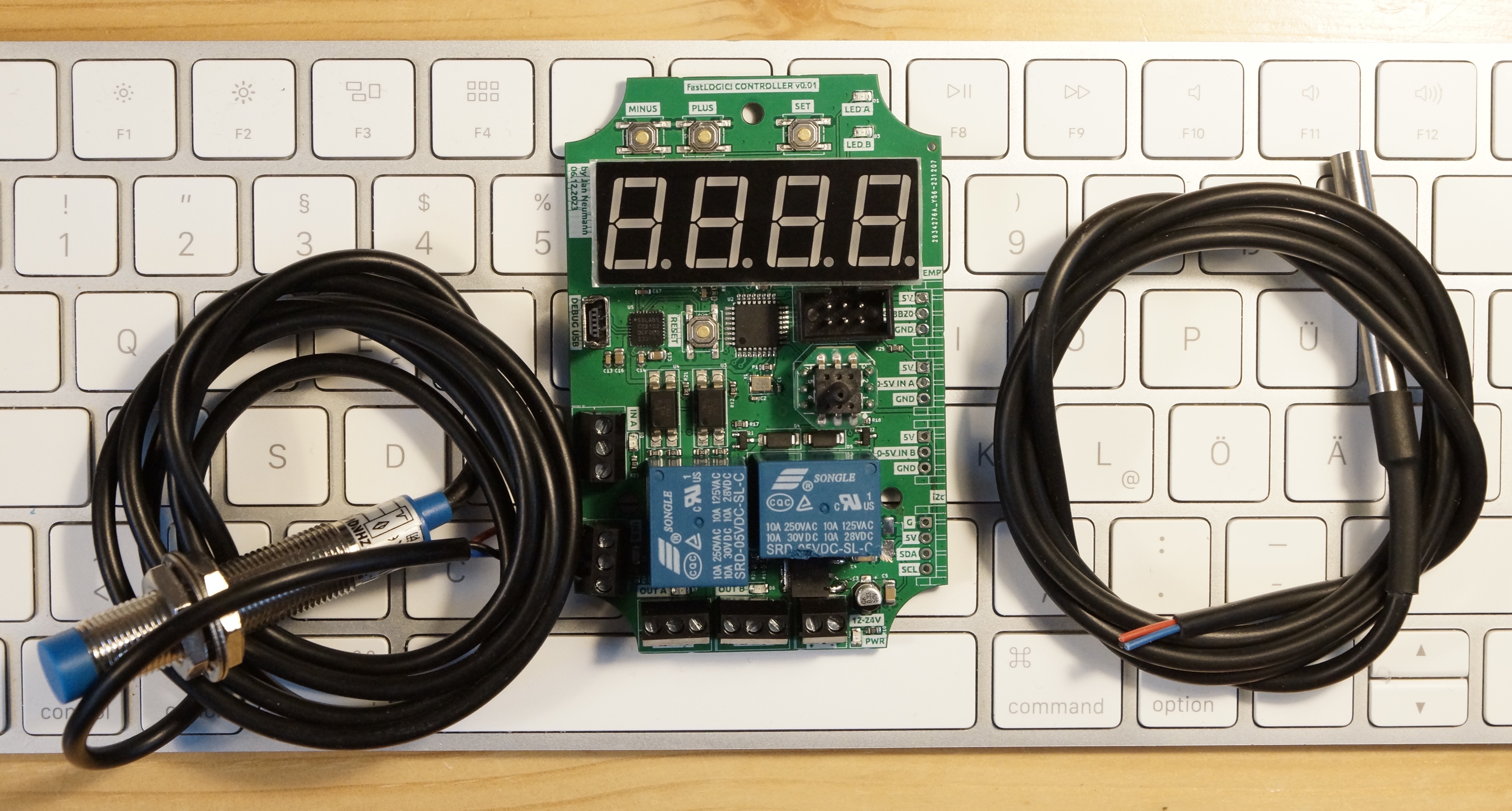
FastLOGIC! is designed to cater to the automation needs of various applications, especially those with modest logic requirements. Its purpose is to streamline smaller projects by eliminating the need for excessive error-prone breadboarding while retaining flexibility and adaptability.
Use cases could be one of these:
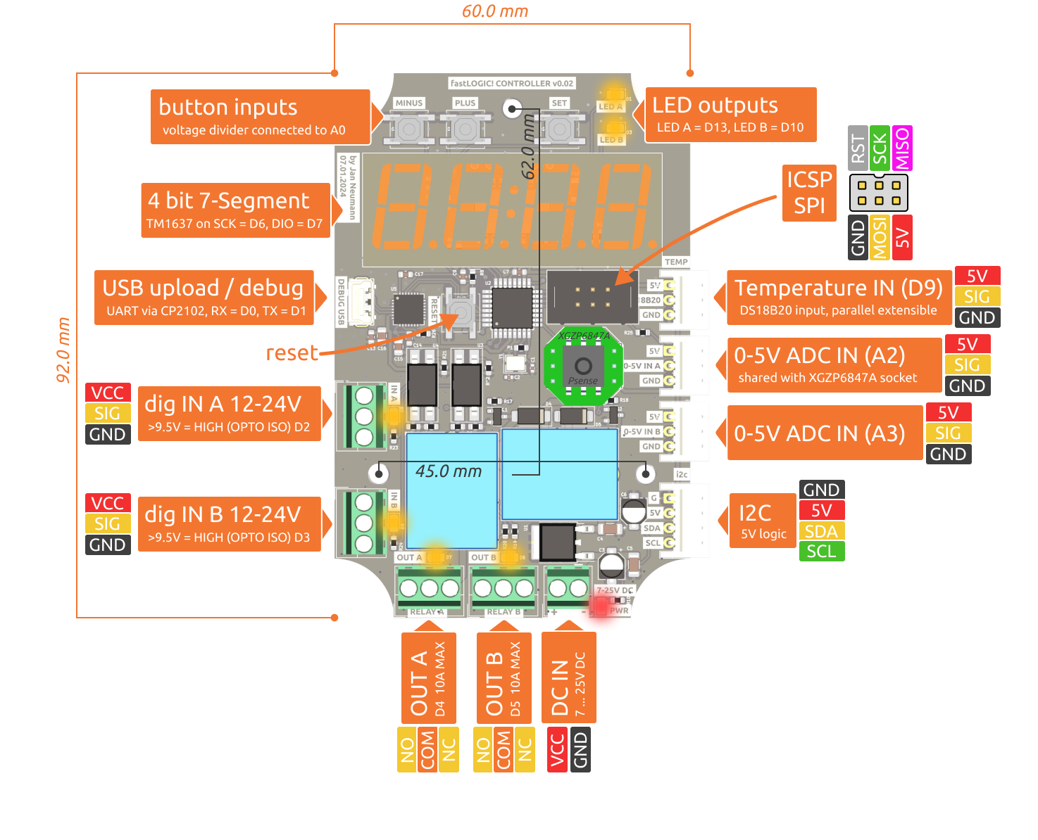
The Arduino library can be used to get started. A few example sketches show what fastLOGIC! is capable of, how to read sensor data and how to write outputs to the LEDs and relays.
The library covers most cases, but if you want to write or read directly from or to the pins:
// fastLOGIC! pin mapping
DIGITAL_IN_A = D2;
DIGITAL_IN_B = D3;
RELAY_A_OUT = D5;
RELAY_B_OUT = D4;
TM1637_SCK = D6;
TM1637_DIO = D7;
DS18B20_DATA = D9;
LED_B_OUT = D10;
LED_A_OUT = D13;
VOLTAGE_SENS_IN = A0;
BUTTONS_IN = A1;
ANALOG_IN_A = A2;
ANALOG_IN_B = A3;
If you want to use the 7-segment display, use this library.
The part numbers in the KiCAD files are LCSC part numbers. This means you can order directly from JLCPCB using the manufacturing files in the production folder. I typically opt for SMT parts exclusively due to the high cost associated with THT assembly and also because not all the required parts are readily available in stock.
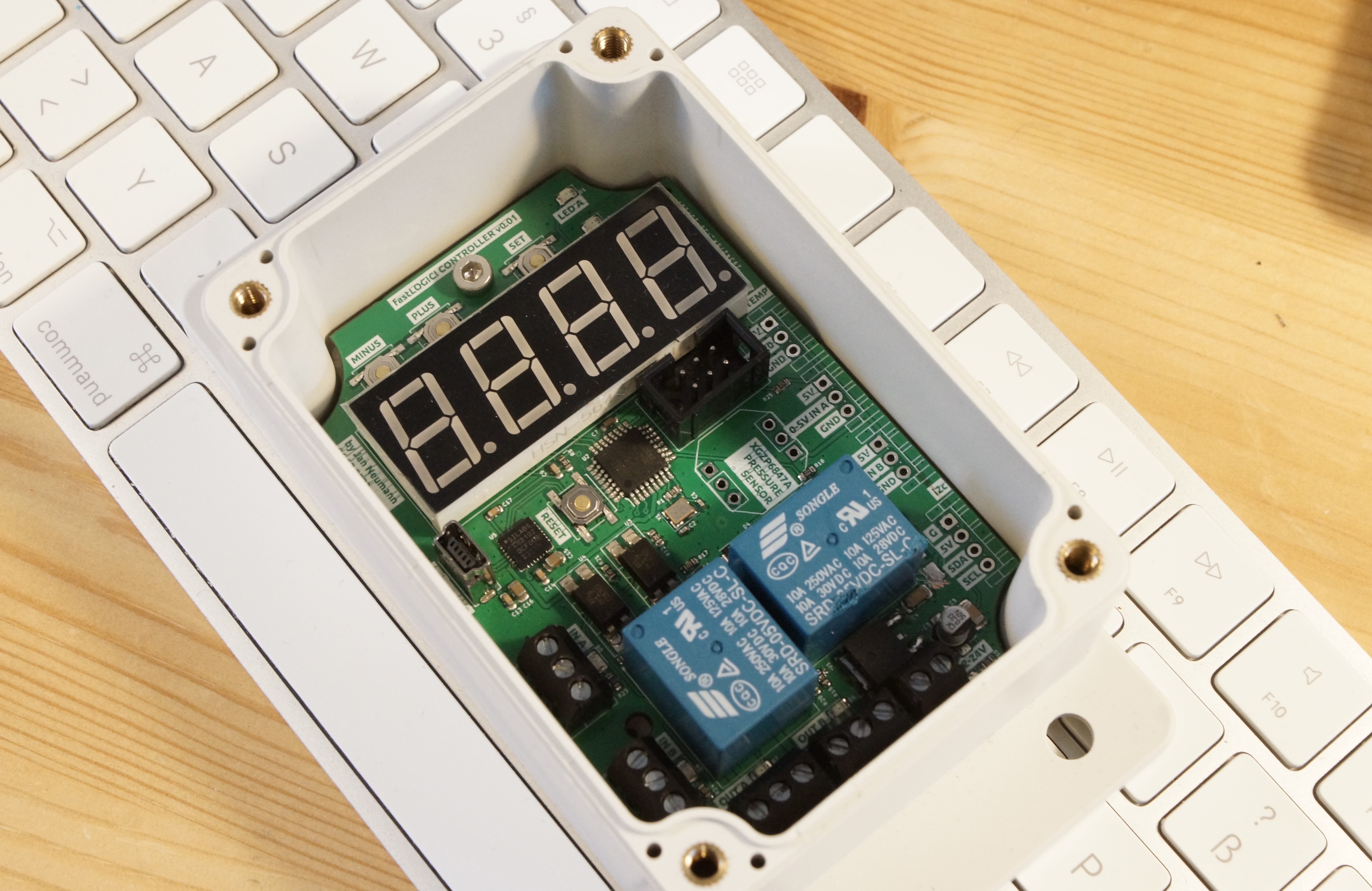
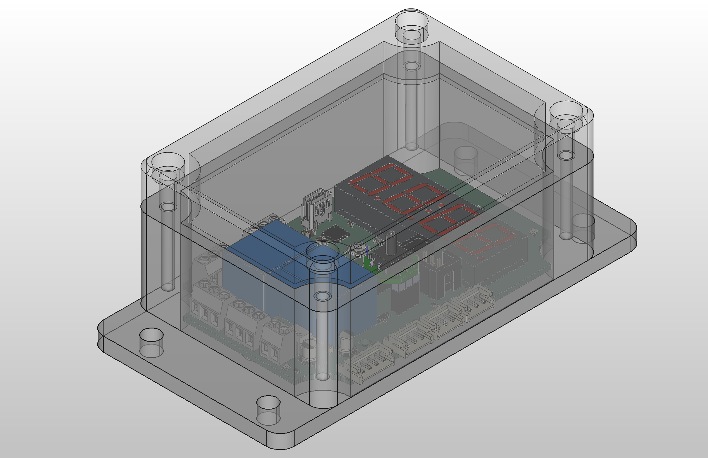
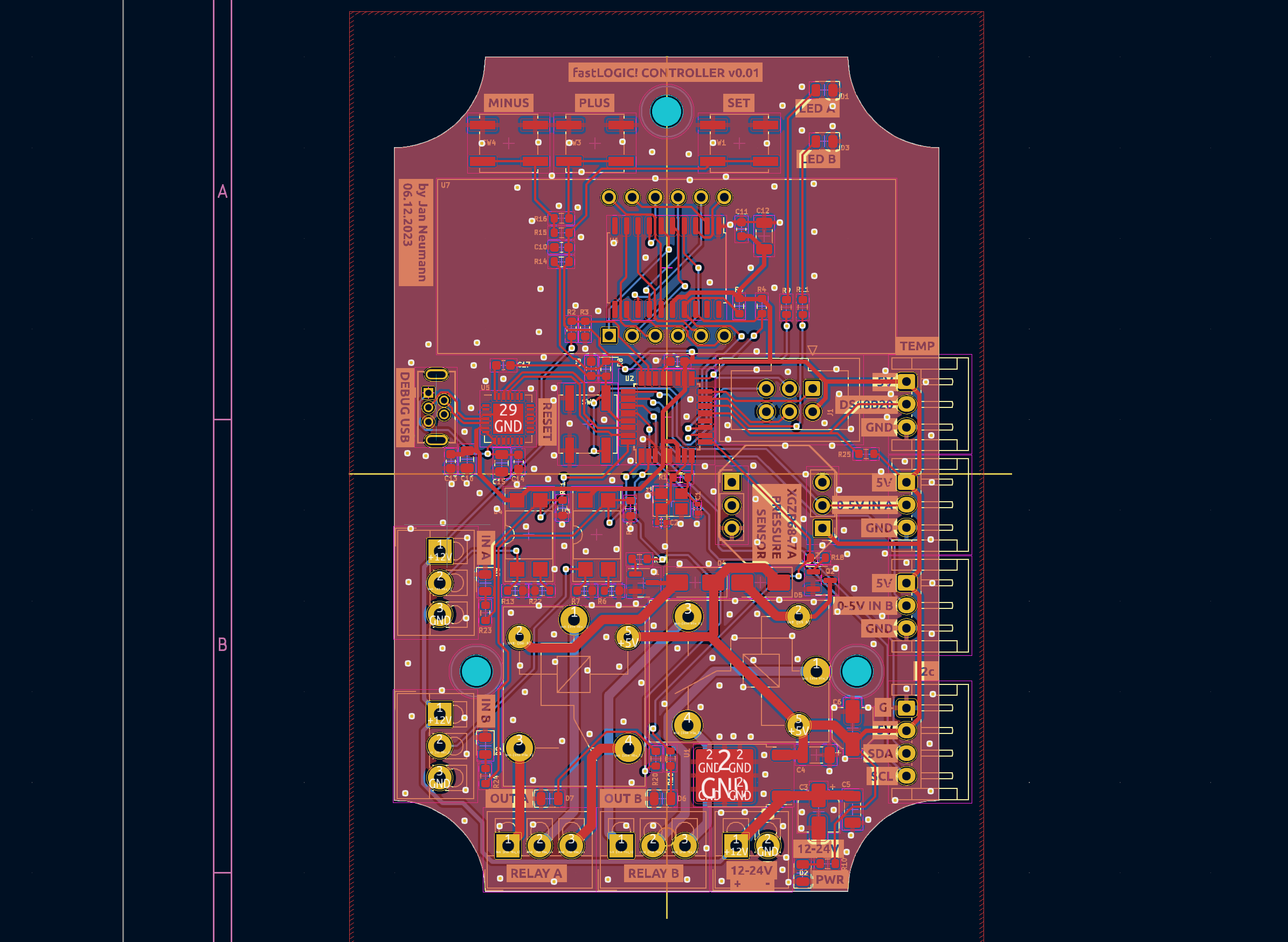
The placement is largely self-explanatory. If you find yourself uncertain, you can refer to the images provided below or utilize the 3D view feature in KiCAD for further clarification.

Follow the project on hackaday.io!

| Qty | Value | Footprint | References |
|---|---|---|---|
| 9 | R10k | Resistor_SMD:R_0603_1608Metric | R2, R4, R5, R7, R8, R12, R13, R14, R21 |
| 8 | R330 | Resistor_SMD:R_0603_1608Metric | R9, R10, R11, R15, R19, R20, R23, R24 |
| 7 | C100nF | Capacitor_SMD:C_0603_1608Metric | C7, C9, C10, C11, C13, C14, C17 |
| 3 | LED_OUT_B | LED_SMD:LED_0805_2012Metric | D6, D8, D9 |
| 3 | MH | MountingHole:MountingHole_3.2mm_M3_DIN965 | H1, H3, H5 |
| 3 | R2.2k | Resistor_SMD:R_0603_1608Metric | R3, R17, R18 |
| 2 | C100nF | Capacitor_SMD:C_1206_3216Metric | C4, C5 |
| 2 | C10uF | Capacitor_SMD:C_0805_2012Metric | C15, C16 |
| 2 | C18pF | Capacitor_SMD:C_0402_1005Metric | C1, C2 |
| 2 | C_330nF | Capacitor_SMD:CP_Elec_4x5.4 | C3, C6 |
| 2 | D | Diode_SMD:D_SMA | D4, D5 |
| 2 | EL817 | Package_DIP:DIP-4_W8.89mm_SMDSocket_LongPads | U3, U4 |
| 2 | MMBT5551L | Package_TO_SOT_SMD:SOT-23 | Q1, Q2 |
| 2 | R4.7k | Resistor_SMD:R_0603_1608Metric | R25, R26 |
| 2 | R470 | Resistor_SMD:R_0603_1608Metric | R6, R22 |
| 2 | SANYOU_SRD_Form_C | Relay_THT:Relay_SPDT_SANYOU_SRD_Series_Form_C | K1, K2 |
| 1 | 0-5V_ANALOG_IN_A | Connector_JST:JST_EH_S3B-EH_1x03_P2.50mm_Horizontal | J10 |
| 1 | 0-5V_ANALOG_IN_B | Connector_JST:JST_EH_S3B-EH_1x03_P2.50mm_Horizontal | J13 |
| 1 | 12-24V | TerminalBlock_4Ucon:TerminalBlock_4Ucon_1x02_P3.50mm_Vertical | J4 |
| 1 | 12-24V_IN_A | TerminalBlock_4Ucon:TerminalBlock_4Ucon_1x03_P3.50mm_Vertical | J8 |
| 1 | 12-24V_IN_B | TerminalBlock_4Ucon:TerminalBlock_4Ucon_1x03_P3.50mm_Vertical | J9 |
| 1 | ATmega328P-A | Package_QFP:TQFP-32_7x7mm_P0.8mm | U2 |
| 1 | AVR-ISP-6 | Connector_IDC:IDC-Header_2x03_P2.54mm_Vertical | J1 |
| 1 | C100uF | Capacitor_SMD:C_1206_3216Metric | C12 |
| 1 | CA56-12SRWA | Display_7Segment:CA56-12SRWA | U7 |
| 1 | CP2102N-Axx-xQFN28 | Package_DFN_QFN:QFN-28-1EP_5x5mm_P0.5mm_EP3.35x3.35mm | U5 |
| 1 | Crystal_25MHz | Crystal:Crystal_SMD_3225-4Pin_3.2x2.5mm | Y1 |
| 1 | DS18B20 | Connector_JST:JST_EH_S3B-EH_1x03_P2.50mm_Horizontal | J3 |
| 1 | I2C | Connector_JST:JST_EH_S4B-EH_1x04_P2.50mm_Horizontal | J5 |
| 1 | LED_A | LED_SMD:LED_0805_2012Metric | D1 |
| 1 | LED_B | LED_SMD:LED_0805_2012Metric | D3 |
| 1 | LED_OUT_A | LED_SMD:LED_0805_2012Metric | D7 |
| 1 | LED_PWR | LED_SMD:LED_0805_2012Metric | D2 |
| 1 | LM78M05_TO252 | Package_TO_SOT_SMD:TO-252-2 | U1 |
| 1 | MINUS | Button_Switch_SMD:SW_Push_1P1T_NO_CK_KSC7xxJ | SW4 |
| 1 | PLUS | Button_Switch_SMD:SW_Push_1P1T_NO_CK_KSC7xxJ | SW3 |
| 1 | PRES_SENS_BOTTOM | Connector_PinHeader_2.54mm:PinHeader_1x03_P2.54mm_Vertical | J11 |
| 1 | PRES_SENS_TOP | Connector_PinHeader_2.54mm:PinHeader_1x03_P2.54mm_Vertical | J12 |
| 1 | R1M | Resistor_SMD:R_0603_1608Metric | R1 |
| 1 | R620 | Resistor_SMD:R_0603_1608Metric | R16 |
| 1 | RELAY_OUT_A | TerminalBlock_4Ucon:TerminalBlock_4Ucon_1x03_P3.50mm_Vertical | J15 |
| 1 | RELAY_OUT_B | TerminalBlock_4Ucon:TerminalBlock_4Ucon_1x03_P3.50mm_Vertical | J14 |
| 1 | SET | Button_Switch_SMD:SW_Push_1P1T_NO_CK_KSC7xxJ | SW1 |
| 1 | TM1637 | Package_SO:SOP-20_7.5x12.8mm_P1.27mm | U6 |
| 1 | USB_B_Mini | Connector_USB:USB_Mini-B_Tensility_54-00023_Vertical | J6 |
| 1 | reset | Button_Switch_SMD:SW_Push_1P1T_NO_CK_KSC7xxJ | SW2 |
It measures 60 × 92 mm and has 2 copper layers, 1.6 mm thick.
83 parts, built around the ATMEGA328P-AU, TM1637, DS18B20 and EL817. The full list of its parts is on this page, with links to each part's symbol and footprint where PCBKit's library has them.
From the Neumi/fastLOGIC repository on GitHub, at the commit this page was made from: the board is hardware/version001/fastLOGIC/fastLOGIC.kicad_pcb and its schematic hardware/version001/fastLOGIC/fastLOGIC.kicad_sch. PCBKit opens the board in the browser, with nothing to install.
Its repository publishes it under the MIT licence: you may reuse it on that licence's terms (keep the author's notice, and for a copyleft licence share your changes alike).
Neumi/fastLOGIC
An affordable Arduino-based board designed for straightforward (industrial) logic control, ideal for building small-scale automation and control solutions.


Neumi/ethersweep
Open Source, easy to use Ethernet connected stepper motor controller. Built in FreeCAD, KiCAD and Arduino.

TheUnproductive/FrameworkHDMICaptureCard
This Project aims to bring a native HDMI Capture Card to the Framework architecture.

Asapgiri/kbb-keyboard
Keep in mind, that first the Atmega32u4 will need a bootloader, witch is programmed trough the bootloader pins. We had to program it with an Esp32-C3-mini, witches Arduino ISA codes I will upload here under the folder…


AlisonTristao/KynoWave
Dispositivo IoT para monitoramento do nivel de ruído em ambientes (2º lugar na maratona de inovação 2026/1 - Arena Ação Junior)

Neumi/open_echo
Open Source echo sounder / depth sounder / SONAR for bathymetry and research. Arduino based and compatible.

augustinzaininger/photocatalysisManagement
PCB Layouts, firmware and software for management of photocatalysis experimental system consisting of MFCs, Solenoid Valves etc