

2 layers45.7 × 31.8 mm
LEDx16 board
tardate/LittleArduinoProjects
a collection of "Little Electronic & Arduino Projects", most involving electronics or an Arduino in one way or another!
36 parts803MIT
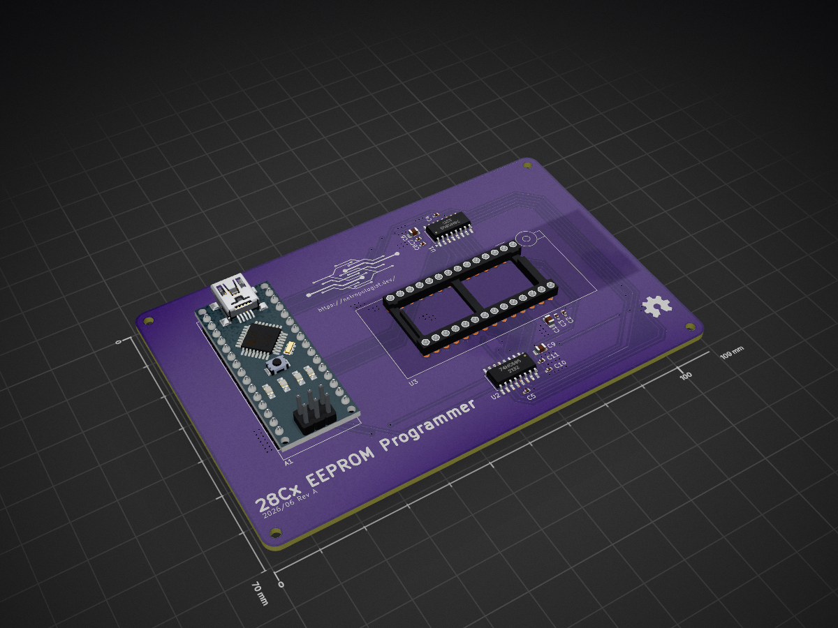
 NetworkEntropologist/28c-eeprom-programmer3
An EEPROM programmer for the 28Cx series of EEPROMs.
Rom programmer is an open-source printed circuit board by NetworkEntropologist, from the NetworkEntropologist/28c-eeprom-programmer repository on GitHub. It is a 2-layer board of 109 × 70 mm with 21 parts on 47 nets, routed with 226 tracks and 93 vias.
It is built around the 74HC595. Its parts include 11 capacitors and 3 ICs. It belongs with the interfaces and adapters boards and the AVR (ATmega, ATtiny) boards of this library.



A parallel EEPROM programmer for the 28C family, built around an Arduino Nano. Simply drop an EEPROM into the ZIF socket, connect the Nano over USB, and burn a ROM image onto it from your computer.
If you've watched Ben Eater's 8-bit computer series, this will look familiar. That's where the idea came from. I wanted a proper PCB instead of the breadboard version, and a ZIF socket so I'm not bending chip pins every time I swap an EEPROM.
This is a personal project that I'm putting it up in case someone else finds it useful or interesting. I'm not planning to write full documentation right now, and I might not ever get to it. So for the moment, the board files and the code are the documentation.
If you find a bug, or you get it working with a chip I haven't tested, feel free to open an issue or a pull request. Just don't expect a fast reply — this is a side thing I work on when I have time.
For a number of years I have been interested in retrocomputing, when one day I stumbled across Ben Eater's YouTube channel. Following his series on espeially the 6502 breadboard computer project I wanted to start building this for myself, or rather using this as inspiration to design and build my own 6501 computer, and this EEPROM Programmer seemed like the best place to start, as this would be a required tool for pretty much everything else.
I have to mention at this point, two other related projects that I used heavily for both inspiration, as well as for insights into how other creators tackled this:
So thanks to both of them. My version borrows ideas from each and mixes in what I wanted out of it.
Short answer? Yes. First test on the PCB, after soldering it, was to attempt burning a copy of Wozmon onto the IC, which checked out byte exact. Turns out Wozmon is a really great test, as the contents is very well known and documented all over the internet.
Anything in the 28C family that follows the 28C64 pinout should work. That being said, I've only tested it with a 28C64 so far. So treat everything else as should work rather than known good. If you run it with a 28C16 or 28C256, I'd like to hear how it goes.
The main parts, leaving out the passives:
hardware/ — the full KiCad project (schematic and PCB)firmware/ — the Arduino firmware for the Nanosoftware/ — the host-side Python that talks to the boardThe KiCad project lives in hardware/. Open it in KiCad, export the Gerbers, and send them off to whichever fab you like. I used JLCPCB with a purple soldermask and had no trouble — DRC passed and the boards were fine.
The firmware in firmware/ was written with PlatformIO, not the regular Arduino IDE. So the easiest way to build and upload is with PlatformIO (either the VS Code extension or the CLI). Open the firmware/ folder as a PlatformIO project, plug in the Nano, and run the upload.
If you're using an older Nano clone, you may need to point the build at the old bootloader, otherwise the upload will fail. That's set in the platformio.ini.
This assumes you've used PlatformIO before. If you haven't, their docs cover installing it and uploading to a board better than I could here.
The host software is in software/ and it's written in Python. Fair warning: it's still very much a work in progress. Because of that I'm not going to write down a fixed set of commands here that might change next week. Have a look in the software/ folder and read the code to see how it works for now.
I'm planning to rewrite this side in Rust later on, so expect it to change.
hardware/): CERN-OHL-S v2firmware/ and software/): MIT| Qty | Value | Footprint | References |
|---|---|---|---|
| 8 | 0.1uF | Capacitor_SMD:C_0402_1005Metric_Pad0.74x0.62mm_HandSolder | C2, C3, C4, C5, C7, C8, C10, C11 |
| 4 | MountingHole | MountingHole:MountingHole_2.2mm_M2 | H1, H2, H3, H4 |
| 3 | 1uF | Capacitor_SMD:C_0805_2012Metric_Pad1.18x1.45mm_HandSolder | C1, C6, C9 |
| 2 | 74HC595 | Package_SO:SOP-16_4.55x10.3mm_P1.27mm | U1, U2 |
| 1 | 28C256 | Socket:DIP_Socket-28_W11.9mm_W12.7mm_W15.24mm_W17.78mm_W18.5mm_3M_228-1277-00-0602J | U3 |
| 1 | Arduino_Nano_v2.x | Module:Arduino_Nano | A1 |
| 1 | LOGO | tne logo tiny | G*** |
The 20 most common of 21 parts.
It measures 109 × 70 mm and has 2 copper layers, 1.6 mm thick.
21 parts, built around the 74HC595. The full list of its parts is on this page, with links to each part's symbol and footprint where PCBKit's library has them.
From the NetworkEntropologist/28c-eeprom-programmer repository on GitHub, at the commit this page was made from: the board is hardware/smd/rom-programmer.kicad_pcb and its schematic hardware/smd/rom-programmer.kicad_sch. PCBKit opens the board in the browser, with nothing to install.
Its repository states no licence, so its author keeps all rights: ask NetworkEntropologist before reusing the design.
tardate/LittleArduinoProjects
a collection of "Little Electronic & Arduino Projects", most involving electronics or an Arduino in one way or another!

ChrisChrisLoLo/beyblock20
The magnetic, modular, 20-key macropad that can join together to form an ortholinear board

slu4coder/Minimal-64x4-Home-Computer
My DIY TTL home computer with VGA and PS/2 and 4x the processing power of a Commodore C64 or Apple II.

electroniceel/protoboard
Advanced protoboard layout with 1.27mm pitch for smd parts

TobleMiner/DC-UPS
A small DC UPS, designed to keep small appliances like consumer network equipment running during power outages


