4 layers100 × 66 mm

 necroware/nwX287236
Drop-In replacement for Dallas, Benchmarq, Odin and other RTC modules
NwX287 is an open-source printed circuit board by necroware, from the necroware/nwX287 repository on GitHub, published under the GPL-3.0 licence. It is a 2-layer board of 18.3 × 31.1 mm with 5 parts on 26 nets, routed with 112 tracks and 17 vias.
It is built around the BQ4285EP and CR1220-2. Its parts include 2 ICs and 1 crystal.


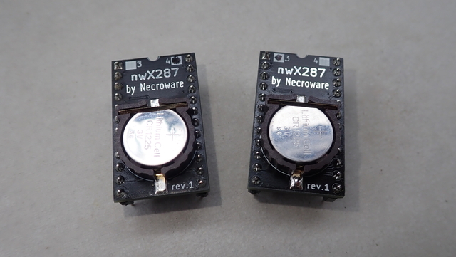
This is a drop-in replacement for RTC modules with solid body. Such modules were widely used on 486 and Pentium mainboards back in the days. After so many years the battery inside of such modules got empty and there is no way to exchange it. With empty battery BIOS settings can not be saved and so many mainboards can't even boot properly. This alternative solution has a socket for CR1225 and the battery can be easily replaced again, when it gets empty. This module can be used with BQ3285, BQ4285 or pin compatible RTC chips, dependent on the requirements. This module was tested only with the named ICs, but it should be also compatible with DS1385, which has additional 2KB of NVRAM and was used on many microchannel and EISA mainboards.
This part should be compatible with following RTC modules:
Video: https://www.youtube.com/watch?v=svPNxILeQEw
Pay attention, which RTC IC you need. Most of the mainboards with an RTC module need BQ3285, but some EISA mainboards require BQ4285 with chip enable signaling on pins 21/22 to control external memory. The Benchmarq ICs are easier to find today, that's why they are proposed, but there are some compatible ICs existing which can be used instead as well:
This module can be also used as a replacement for the Hitachi HD146818P RTC chip which was not only used in many PC mainboards, but also in other devices and home computers like the BBC Master. On some devices the pin 1 has to be pulled up to pin 24 (VCC, Motorola Mode) or down to pin 12 (Ground, Intel Mode) using a 10k resistor. This was tested by Adrian on his YT channel (he used a simple bodge wire, but it's safer to use a resistor: https://youtu.be/2Sgleturods?t=2970)
Important: some mainboards seem to use /RCL pin 21, so cut it first if you are sure, that your mainboard doesn't use it.
Dependent on which RTC chip you are using you have to cut off some pins on the module. If you are using BQ3285, you need to remove pins 2,3,16,20,21,22. When using BQ4285 you need to remove pins 2,3,16,20.
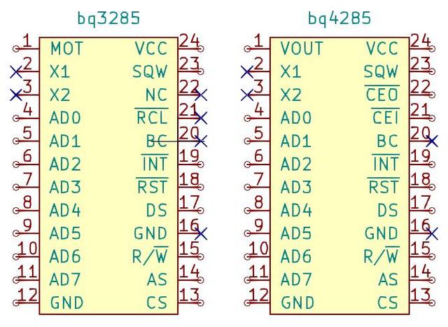
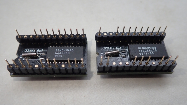
The BQ3285 and most of the compatible chips can work in two modes Motorola and Intel. The Motorola mode was usually used on home computers with Motorola CPU and on x86 compatible PCs used the Intel mode. The BQ3285 and most compatible chips have auto detection feature for the mode. If pin 1 is pulled high, then the chip will work in Motorola mode and if it is set to low, then the Intel mode is selected. Unfortunately very old systems used original RTC chips, where the pin 1 was floating and the chips were hard wired internally to be always either in Motorola or Intel mode. On this nwX287 replacement module pin 1 on the PCB is connected to the pin 1 of the chip, so the mode selection should work, however if accordant connection on the mainboard is floating, the chip will go into the default mode, which is Intel. That will be a problem on older systems, which expect the chip to be in Motorola mode. Therefore an optional jumper was introduced on the module to force a particular mode if needed. If the module is not workin in your system, try to put a solder blob as required.
| Part | # | Description |
|---|---|---|
| U1 | 1 | Real-Time Clock BQ3285S or BQ4285S SO-24 |
| Y1 | 1 | Crystal oscillator 32.768kHz 6pF |
| BT1 | 1 | CR1220 / CR1225 SMD battery holder |
It measures 18.3 × 31.1 mm and has 2 copper layers, 1.6 mm thick.
5 parts, built around the BQ4285EP and CR1220-2. The full list of its parts is on this page, with links to each part's symbol and footprint where PCBKit's library has them.
From the necroware/nwX287 repository on GitHub, at the commit this page was made from: the board is kicad/nwX287.kicad_pcb and its schematic kicad/nwX287.kicad_sch. PCBKit opens the board in the browser, with nothing to install.
Its repository publishes it under the GPL-3.0 licence: you may reuse it on that licence's terms (keep the author's notice, and for a copyleft licence share your changes alike).


luftaquila/monolith
DIY wireless real-time datalogging platform for Student Formula and Baja.

rusefi/uaefi
🔴Community support ONLY 🔴 https://www.facebook.com/groups/rusEfi 🔴 Discord🔴 Commercial Support 🔴


