
2 layers45 × 76 mm

 eivindbohler/tinyllama2138
A tiny x86 retro computer
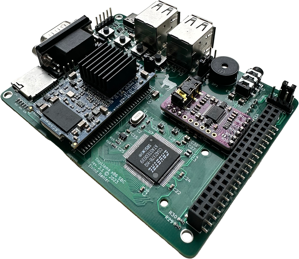
TinyLlama is an open-source printed circuit board by eivindbohler, from the eivindbohler/tinyllama2 repository on GitHub, published under the GPL-3.0 licence. It is a 4-layer board of 100 × 77 mm with 139 parts on 306 nets, routed with 1,842 tracks and 168 vias.
It is built around the CR1220-2. Its parts include 46 capacitors, 38 resistors, 14 connectors, 8 ICs and 6 switches. It belongs with the ESP8266 boards of this library.
Note
YouTube walkthrough + setup coming soon!
The goal of the TinyLlama project is:
Last year I released version 1 of the TinyLlama.
While I was very happy with it and it worked great, there were a couple of things I felt were still missing + a few bugs.
The two main new features in version 2 are:
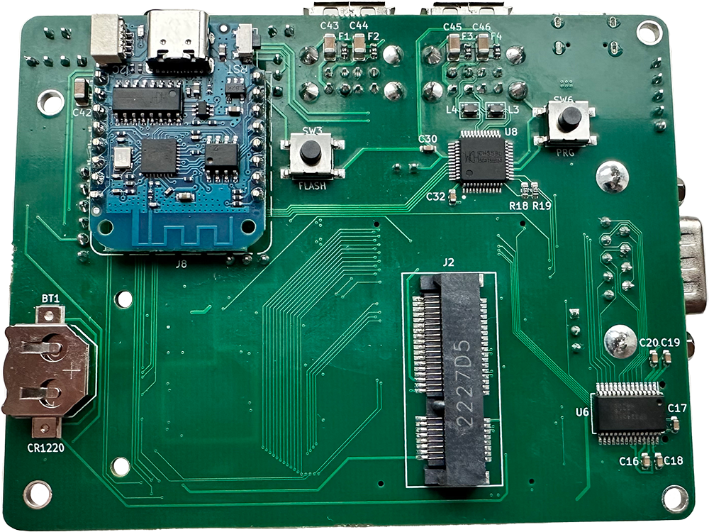
Both the CH559 and the ESP8266 can be easily re-flashed/programmed in-place.
Look at Programming the CH559 and Programming the ESP8266.
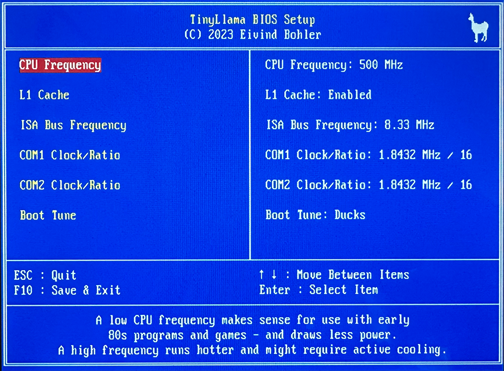
Full BOM (bill of materials) can be found in the wiki.
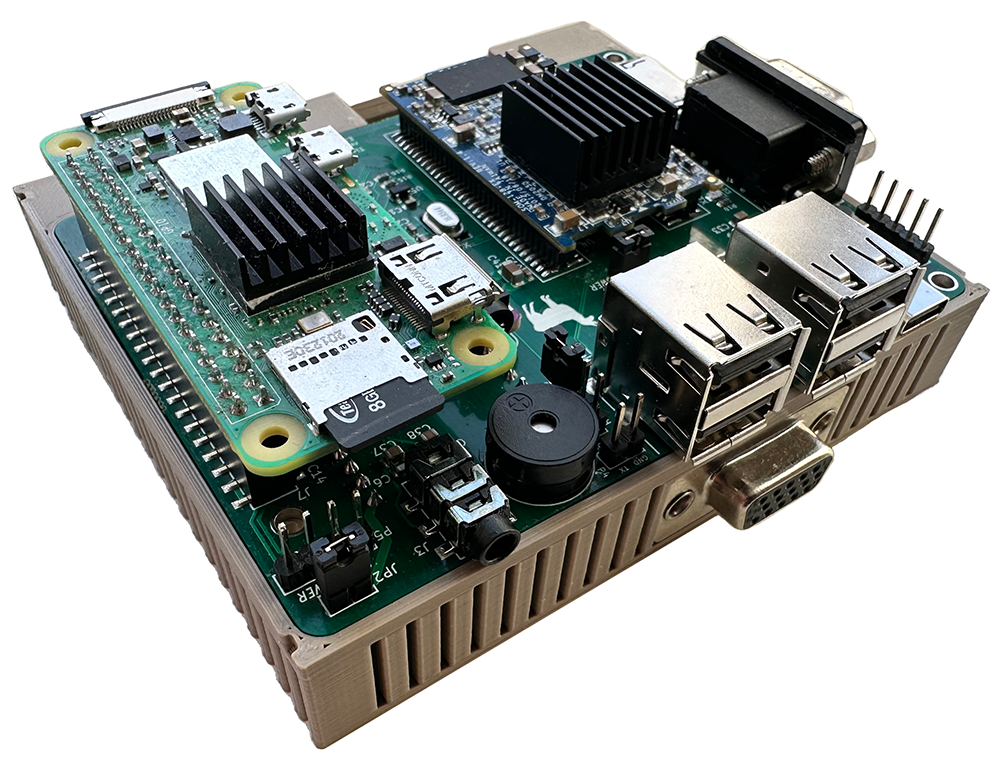
Solder all components onto the TinyLlama rev2.1 PCB. As always, it's easier to start with the low-profile ones first, like resistors and capacitors. If you're willing to spend slightly more, I recommended you let the PCB manufacturer pre-assemble most of the common components for you. Plus, some of the SMD components can be a bit tricky to solder. Take a look at the wiki for more in-depth assembly instructions.
hidman-binary folder. Alternatively, get the latest source code from the official repo and compile it yourself.WCHISPTool_Setup.exe from WCH's website. Unfortunately, this tool only supports Windows. If you're on macOS or Linux, maybe try using virtualization software, or even another computer.WCHISPTool_CH54x-55x application.When purchasing the SOM-128-EX module from DMP, its ROM chip comes preinstalled with an Arduino-like bootloader which isn't what we want. Also, the "crossbar" is configured for using the module with the 86Duino Zero/One boards - meaning its default pin layout is completely different from what we need for the TinyLlama.
Follow these steps to flash the ROM with the TinyLlama BIOS for the first time:
INITBIOS.IMG from this repo to the USB drive. Use Balena Etcher, or the command line if you know what you're doing (macOS example):$ diskutil list
(Find your USB drive, eg. /dev/disk2)
$ diskutil unmountDisk /dev/disk2
$ sudo dd if=INITBIOS.IMG of=/dev/rdisk2 bs=1mC:\>anybios w initbios.rom...and reboot.
For subsequent BIOS updates, you can use the ROM's built-in virtual floppy drive available from the boot menu (press F12).
When booted from this you'll only need a regular USB stick (formatted as FAT16/FAT32) containing the new BIOS file.
A note on selecting the DOS type:
I've gone with MS-DOS 6.22 for maximum compatibility.
If you prefer FreeDOS (or another DOS variant), prepare a bootable USB installer disk and use that instead of the built-in virtual floppy.
fdisk from the command prompt to partition the SD/USB drive and set it to be Active.format c: /s /u to format the drive and copy over system files. Finally use fdisk /mbr to make sure the Master Boot Record is correct and the drive should be bootable.DOS folder from A: to C:.CONFIG.SYS and AUTOEXEC.BAT files to your liking, or more conveniently, just run the SETUP.BAT script that'll do this for you. The provided config files lets you choose from a clean boot or a QEMM-based one with XMS, EMS and 631 kB of free conventional memory.CS4237B and UNISOUND folders from this GitHub repo over to your SD/USB boot drive and start the system.RESOURCE.EXE command below and check that you get the same output:C:\>cd cs4237b
C:\CS4237B>resource /f=0x120 /r=cs4237b.asm /e
Reading data from CS4237B.ASM
Length = 292 Programming EEPROM Block: 1 2 EEPROM programmed
Verifying EEPROM:
Verifying CS4237B.ASM against EEPROM . . . Verified OKAYBLASTER environment variable is set and UNISOUND.COM command is called from AUTOEXEC.BAT. Note that the 8-bit DMA channel is 1 and the IRQ is 7:SET BLASTER=A220 I7 D1 P330 T4
C:\UNISOUND\UNISOUND.EXE /V60 /VW60 /VF60 /VL60 /VP60 /VC0 /VM0Universal ISA PnP Sound Card Driver for DOS v0.76f. (c) JazeFox 2019-21
-----------------------------------------------------------------------
PnP card found: [CSC7537] CS4237B
BLASTER environment var found! Loading settings...
ADD:220 WSS:534 OPL:388 IRQ:7 DMA:1/1 MPU:330/I9 CTR:120 JOY:200
Initialization done.
Crystal Mixer [VOL:85 WAV:80 FM:80 LIN:0 CD:0 MIC:0]C:\UNISOUND\UNISOUND.TXT file for further guidance.If you've installed mt32-pi on a Raspberry Pi Zero 2 and connected it to the TinyLlama, it should be ready to go using IO port 330. Use the third button from the left (labeled "SYNTH_SW" on the PCB) to switch between MT-32 and General MIDI mode.
If you want to play old games that require "MPU-401 Intelligent Mode" (Sierra games, Monkey Island 1, etc), try running SoftMPU:
C:\SOFTMPU\>softmpu /mpu:330 /sb:220 /irq:7If you want to hook up an I²C OLED display to the mt32-pi, there's a pin header on the TinyLlama labeled "I2C_OLED". The order of the pins from 1 to 4 is: GND, VCC, SCL, SDA with pin 1 being the one closest to the 3.5mm audio jack.
There's a section in the wiki dedicated to this, take a look.
For an in-depth discussion of the various components, installation, configuration, etc, take a look at the wiki.
This project is indended for people with a fair bit of hardware- and DOS knowledge. If you have questions or need help, please look at the wiki and FAQ section first.
Coming.
In the mean time feel free to post an issue if you have tips, suggestions or want to report an error.
GNU General Public License v3.0
Development thread: Vogons
Mastodon: @eivindbohler@techhub.social
Twitter: @eivindbohler
YouTube: @eivindbohler
Many thanks to
| Qty | Value | Footprint | References |
|---|---|---|---|
| 22 | 0.1uF | Capacitor_SMD:C_0603_1608Metric | C10, C11, C12, C13, C14, C15, C16, C17, C18, C19, C20, C21, C22, C23, C24, C25 +6 |
| 8 | 4.7k | Resistor_SMD:R_0603_1608Metric | R14, R15, R16, R17, R18, R19, R20, R21 |
| 8 | 47k | Resistor_SMD:R_0603_1608Metric | R31, R32, R33, R34, R35, R36, R37, R38 |
| 8 | 47uF | Capacitor_SMD:C_1206_3216Metric | C39, C40, C41, C42, C43, C44, C45, C46 |
| 6 | 10uF | Capacitor_SMD:C_0805_2012Metric | C33, C34, C35, C36, C37, C38 |
| 6 | 33 | Resistor_SMD:R_0603_1608Metric | R2, R3, R4, R5, R6, R7 |
| 4 | 1nF | Capacitor_SMD:C_0603_1608Metric | C3, C4, C5, C6 |
| 4 | 6.8k | Resistor_SMD:R_0603_1608Metric | R24, R25, R26, R27 |
| 4 | F | Fuse:Fuse_0603_1608Metric | F1, F2, F3, F4 |
| 4 | H_HOLE | llama_shared:H_440_HOLE | H1, H2, H3, H4 |
| 4 | L_EMI_FILTER | llama_shared:L_EMI_FILTER_MCM2012B900GBE | L1, L2, L3, L4 |
| 3 | 1k | Resistor_SMD:R_0603_1608Metric | R10, R11, R12 |
| 2 | 10k | Resistor_SMD:R_0603_1608Metric | R28, R29 |
| 2 | 22pF | Capacitor_SMD:C_0603_1608Metric | C1, C2 |
| 2 | 5.1k | Resistor_SMD:R_0603_1608Metric | R22, R23 |
| 2 | FB | Resistor_SMD:R_0805_2012Metric | FB1, FB2 |
| 1 | 0 | Resistor_SMD:R_0603_1608Metric | R1 |
| 1 | 1.5k | Resistor_SMD:R_0603_1608Metric | R13 |
| 1 | 10nF | Capacitor_SMD:C_0603_1608Metric | C8 |
| 1 | 16.9344MHz | llama_shared:X_Crystal_SMD_HC49S-MINI | X1 |
| 1 | 1N4148 | Diode_SMD:D_SOD-323F | D1 |
| 1 | 1uF | Capacitor_SMD:C_0805_2012Metric | C31 |
| 1 | 2.7nF | Capacitor_SMD:C_0603_1608Metric | C7 |
| 1 | 200 | Resistor_SMD:R_0603_1608Metric | R8 |
| 1 | 20k | Resistor_SMD:R_0603_1608Metric | R30 |
| 1 | 3.3uF | Capacitor_SMD:C_0603_1608Metric | C32 |
| 1 | 470 | Resistor_SMD:R_0603_1608Metric | R9 |
| 1 | AudioJack3 | llama_shared:J_AUDIO35_C95463 | J3 |
| 1 | CONN | Diode_SMD:D_0603_1608Metric | D2 |
| 1 | CR1220 | llama_shared:BT_MY-1220-03 | BT1 |
| 1 | D1_MINI | llama_shared:J_WEMOS_D1_MINI | J8 |
| 1 | ESP_DEBUG | llama_shared:P_CONN_01X02_SQUARE | P4 |
| 1 | ESP_POWER | llama_shared:P_CONN_01X02_SQUARE | JP2 |
| 1 | FAN_PWR | llama_shared:P_CONN_01X03_SQUARE | P2 |
| 1 | FLASH | llama_shared:SW_B3FS-1010 | SW3 |
| 1 | GY-PCM5102 | llama_shared:U_GY-PCM5102 | U7 |
| 1 | HID_POWER | llama_shared:P_CONN_01X02_SQUARE | JP3 |
| 1 | I2C_OLED | llama_shared:P_CONN_01X04_SQUARE | P5 |
| 1 | J_MINI_PCIE | llama_shared:J_MINI_PCIE | J2 |
| 1 | J_PI_ZERO | llama_shared:J_CONN_RPI_SMD | J7 |
| 1 | J_USB_C | llama_shared:J_USB_TYPE-C-31-M-12 | J1 |
| 1 | Llama_logo | llama_shared:LLAMA_LOGO | LOGO1 |
| 1 | MICRO_SD | llama_shared:J_MicroSD_TF01A | J4 |
| 1 | NPN | llama_shared:Q_BJT_SOT-23-3 | Q2 |
| 1 | PANEL_BTNS | llama_shared:P_CONN_01X05_SQUARE | P6 |
| 1 | POWER | llama_shared:SW_B3FS-1010 | SW1 |
| 1 | PRG | llama_shared:SW_B3FS-1010 | SW6 |
| 1 | P_DE9M | llama_shared:P_DE9M | P3 |
| 1 | P_SOM-128-EX | llama_shared:P_CONN_SOM-128-EX | P1 |
| 1 | Q_PMOS_GDS | llama_shared:Q_PFET_ENH_SOT-23-3 | Q1 |
| 1 | RESET | llama_shared:SW_B3FS-1010 | SW2 |
| 1 | ROM_SW | llama_shared:SW_B3FS-1010 | SW5 |
| 1 | RX | Diode_SMD:D_0805_2012Metric | D4 |
| 1 | SPEAKER | llama_shared:SP | SP1 |
| 1 | SPKR_VOL | llama_shared:P_CONN_01X03_SQUARE | JP1 |
| 1 | SYNTH_SW | llama_shared:SW_B3FS-1010 | SW4 |
| 1 | TX | Diode_SMD:D_0805_2012Metric | D3 |
| 1 | USB_HID | llama_shared:J_USB_A_C12049 | J6 |
| 1 | USB_NATIVE | llama_shared:J_USB_A_C12049 | J5 |
| 1 | U_74LVC1G04 | llama_shared:U_SOT-23-5 | U4 |
| 1 | U_AMS1117-3.3 | llama_shared:U_SOT-223-3_NOTAB | U2 |
| 1 | U_CH559L | llama_shared:U_QFP-12x12_14x14_Pitch0.5mm | U8 |
| 1 | U_CS4237B-KQ | llama_shared:U_TQFP-100_14x14mm_P0.5mm_HandSoldering | U3 |
| 1 | U_K24C08 | llama_shared:U_SOT-23-5 | U5 |
| 1 | U_MAX16054 | llama_shared:U_TSOT-23-6 | U1 |
| 1 | U_MAX3243 | llama_shared:U_SSOP-28_5.3x10.2mm_P0.65mm | U6 |
It measures 100 × 77 mm and has 4 copper layers, 1.59 mm thick.
139 parts, built around the CR1220-2. The full list of its parts is on this page, with links to each part's symbol and footprint where PCBKit's library has them.
From the eivindbohler/tinyllama2 repository on GitHub, at the commit this page was made from: the board is kicad/TinyLlama.kicad_pcb and its schematic kicad/TinyLlama.kicad_sch. PCBKit opens the board in the browser, with nothing to install.
Its repository publishes it under the GPL-3.0 licence: you may reuse it on that licence's terms (keep the author's notice, and for a copyleft licence share your changes alike).


necroware/nwX287
Drop-In replacement for Dallas, Benchmarq, Odin and other RTC modules

luftaquila/monolith
DIY wireless real-time datalogging platform for Student Formula and Baja.

rusefi/uaefi
🔴Community support ONLY 🔴 https://www.facebook.com/groups/rusEfi 🔴 Discord🔴 Commercial Support 🔴


