2 layers28.3 × 39.8 mm
LevelShifter
gusmanb/logicanalyzer
24 channel, 100Msps logic analyzer hardware and software
21 parts5.1kGPL-3.0

 necroware/mce-adapter140
RGBS converter for MDA, Hercules, CGA and EGA
Mce adapter is an open-source printed circuit board by necroware, from the necroware/mce-adapter repository on GitHub, published under the GPL-3.0 licence. It is a 2-layer board of 62.4 × 31.6 mm with 21 parts on 35 nets, routed with 90 tracks and 0 vias.
Its parts include 9 resistors, 2 capacitors, 2 connectors, 1 IC and 1 diode. It belongs with the interfaces and adapters and retro computing and games boards and the FPGA and CPLD boards of this library.
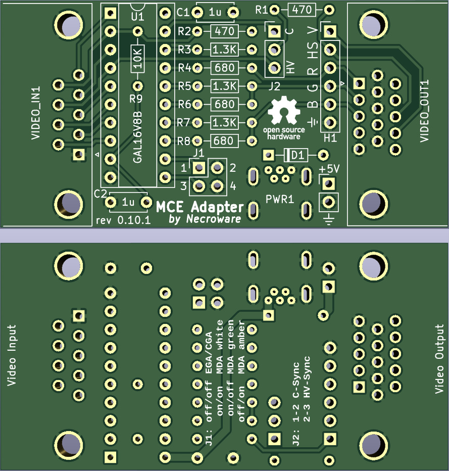
The MCA-Adapter is a device, which can convert MDA (and Hercules), EGA and CGA to analogue RGBS signal. It supports following features.
Youtube Videos:
Because why not? I wanted to get some practice with EDA and I needed such an adapter to test some of my old graphics cards.
If you want to connect your old PC with MDA, CGA or EGA graphics to a more modern VGA display, it's going to be difficult. First of all, this old graphics standards are digital, so RGB information is sent as a bunch of 1 and 0. VGA on the other hand understands only analogue signals, so f.e. the intensity of the red color is defined by some value between two voltages and not by a discrete value. So the first job of this adapter is to translates digital video signals into analogue video signals. However, this is may be not enough, since the horizontal sync signal of the old video standards is not supported by a usual VGA monitor. For this purpose, a very famous upscaler named GBS-8200 and compatible can be used to convert the sync signal to VGA compatible level. However, GBS-8200 expects such called composite sync signal, where horizontal and vertical sync signals are combined. This is, where this adapter comes into place, it doesn't only convert digital RGB signal to analogue, but also composite sync signal from incoming horizontal and vertical signals. Long story short, you will need this adapter to connect a MDA, CGA or EGA graphics card to an analogue RGB monitor, either by using GBS-8200 converter or the adapter standalone, in case your monitor supports horizontal frequencies down to 15kHz.
Well, first of all, I wanted to gain some experience in this. Second, I actually was heavily inspired by a YouTube video by TheRasteri, where he evaluates the output possibilities of an old PC, talks about the technical background and creates his own adapter. You can see the video here:
As I saw his solution with a ROM, I instantly thought, that the same thing can be done using a programmable logic IC, like GAL16V8. It would have some benefits in timing behaviour over a solution with ROM and be also very flexible. So, here it is.
The adapter can convert MDA, Hercules, CGA, 16 colors EGA and 64 colors EGA to standard VGA (RGBHV) or RGBS (combined HV-sync). The sync output frequency is always the same as the input frequency. The adapter can only compose HV-sync, but doesn't actively change it. The digital color signal is converted to analogue color signal, so any analogue RGB monitor should understand it.
ATTENTION: Jumper settings changed compared to previous revisions
Color mode selection J1:
| Mode | 1-2 | 3-4 |
|---|---|---|
| CGA/EGA (15kHz / 21kHz) | OFF | OFF |
| MDA/Hercules white (18kHz) | ON | ON |
| MDA/Hercules green (18kHz) | ON | OFF |
| MDA/Hercules amber (18kHz) | OFF | ON |
Sync selectiom J2:
| Mode | Setting |
|---|---|
| HV-Sync (VGA) | 1-2 |
| C-Sync (Composite) | 2-3 |
| Reference | # | LCSC | Description |
|---|---|---|---|
| C1 C2 | 2 | C2839237 | capacitor 1µF |
| D1 | 1 | C402218 | diode 1N5819 |
| H1 | 1 | C492405 | pin header 1x6 |
| J1 | 1 | C492419 | pin header 2x2 |
| J2 | 1 | C429954 | pin header 1x3 |
| PWR1 | 1 | C46398 | USB-B mini port |
| PWR2 | 1 | C152154 | pin header 1x2 (+5V connector) |
| R1 R2 | 2 | C119317 | resistor 470 Ohm |
| R3 R5 R7 | 3 | C2848597 | resistor 1.3k Ohm |
| R4 R6 R8 | 3 | C119320 | resistor 680 Ohm |
| R9 | 1 | C173139 | resistor 10k Ohm |
| U1 | 1 | C6509 | GAL16V8B (or compatible) |
| VIDEO_IN1 | 1 | C141882 | DB9 female connector (MDA/EGA/CGA) |
| VIDEO_OUT1 | 1 | C75754 | DIB15 female connector (VGA) |
| Qty | Value | Footprint | References |
|---|---|---|---|
| 3 | 1.3K | Resistor_THT:R_Axial_DIN0204_L3.6mm_D1.6mm_P7.62mm_Horizontal | R3, R5, R7 |
| 3 | 680 | Resistor_THT:R_Axial_DIN0204_L3.6mm_D1.6mm_P7.62mm_Horizontal | R4, R6, R8 |
| 2 | 1u | Capacitor_THT:C_Disc_D5.0mm_W2.5mm_P5.00mm | C1, C2 |
| 2 | 470 | Resistor_THT:R_Axial_DIN0204_L3.6mm_D1.6mm_P7.62mm_Horizontal | R1, R2 |
| 1 | +5V | Connector_PinHeader_2.54mm:PinHeader_1x02_P2.54mm_Vertical | PWR2 |
| 1 | 10K | Resistor_THT:R_Axial_DIN0204_L3.6mm_D1.6mm_P7.62mm_Horizontal | R9 |
| 1 | 1N5819 | Diode_THT:D_DO-34_SOD68_P7.62mm_Horizontal | D1 |
| 1 | Conn_01x03_Male | Connector_PinHeader_2.54mm:PinHeader_1x03_P2.54mm_Vertical | J2 |
| 1 | Conn_01x06_Male | Connector_PinHeader_2.54mm:PinHeader_1x06_P2.54mm_Vertical | H1 |
| 1 | Conn_02x02_Odd_Even | Connector_PinHeader_2.54mm:PinHeader_2x02_P2.54mm_Vertical | J1 |
| 1 | DB15_Female_HighDensity_MountingHoles | Connector_Dsub:DSUB-15-HD_Female_Horizontal_P2.29x1.98mm_EdgePinOffset8.35mm_Housed_MountingHolesOffset10.89mm | VIDEO_OUT1 |
| 1 | DB9_Female_MountingHoles | Connector_Dsub:DSUB-9_Female_Horizontal_P2.77x2.84mm_EdgePinOffset7.70mm_Housed_MountingHolesOffset9.12mm | VIDEO_IN1 |
| 1 | GAL16V8B | Package_DIP:DIP-20_W7.62mm_Socket | U1 |
| 1 | USB_B_Mini | Necroware:USB_Mini-B-Jing_Extension_LSCS_C46398 | PWR1 |
The 20 most common of 21 parts.
It measures 62.4 × 31.6 mm and has 2 copper layers, 1.6 mm thick.
21 parts. The full list of its parts is on this page, with links to each part's symbol and footprint where PCBKit's library has them.
From the necroware/mce-adapter repository on GitHub, at the commit this page was made from: the board is kicad/mce-adapter.kicad_pcb and its schematic kicad/mce-adapter.kicad_sch. PCBKit opens the board in the browser, with nothing to install.
Its repository publishes it under the GPL-3.0 licence: you may reuse it on that licence's terms (keep the author's notice, and for a copyleft licence share your changes alike).
gusmanb/logicanalyzer
24 channel, 100Msps logic analyzer hardware and software

mntmn/amiga2000-gfxcard
MNT VA2000, an Open Source Amiga 2/3/4000 Graphics Card (Zorro II/III), written in Verilog


hackclub/OnBoard
💡 Join 1,000 teenagers and make your first PCB with a $100 grant!

drandyhaas/KiCadRoutingTools
A set of Python/Rust tools to aid routing in KiCad

Arrow-air/project-quiver
Project Quiver documentation, designs, and project artifacts.

