

2 layers85 × 85 mm
 nbourre/ATtiny1616WithLineTracker
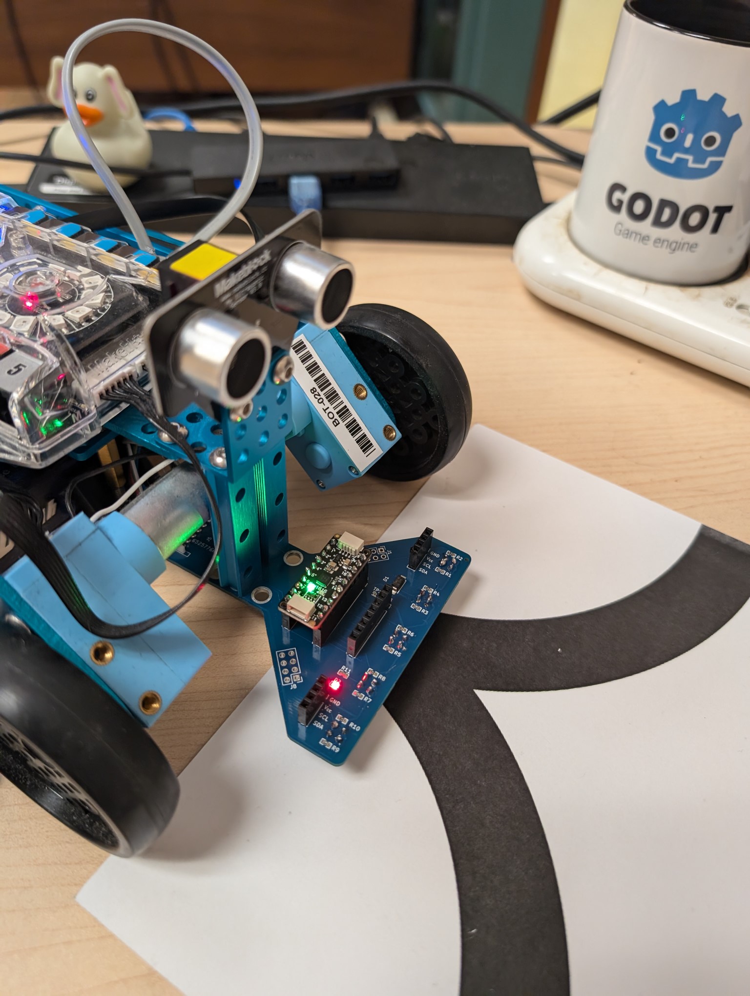
ATtiny1616 Line Tracker compatible with MakeBlock robots
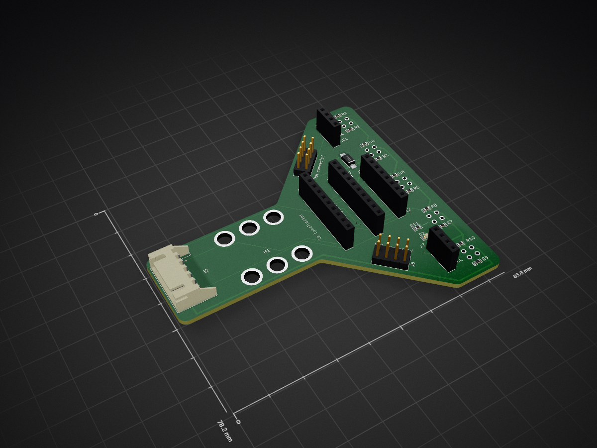
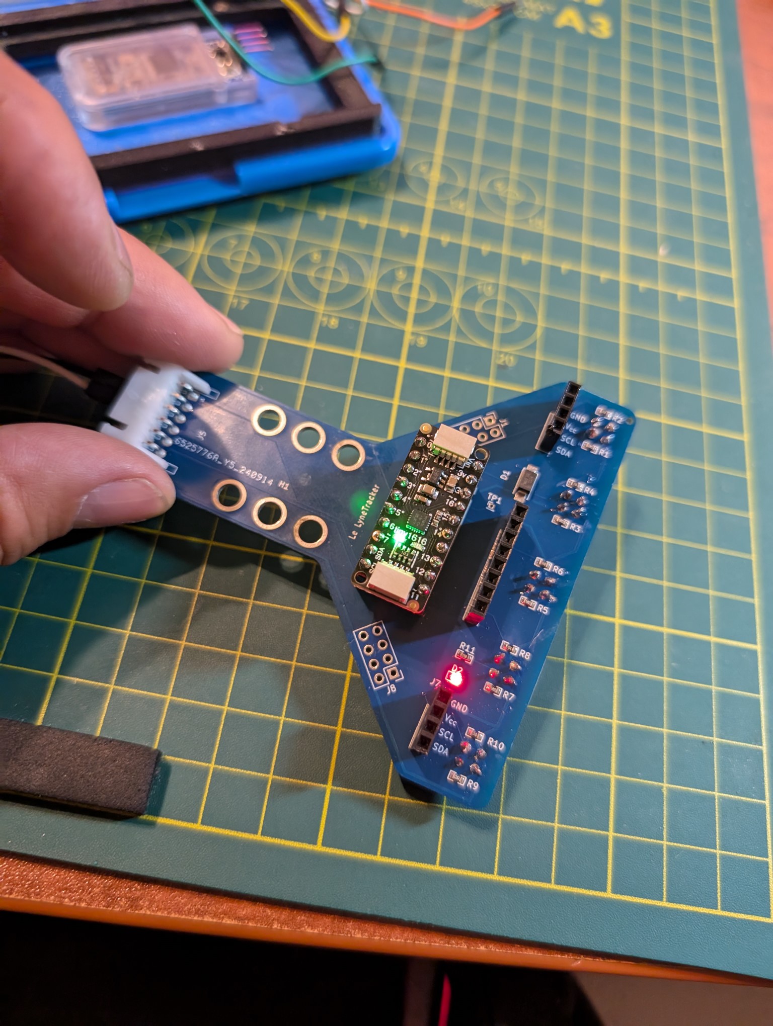
ATtiny1616WithLineTracker is an open-source printed circuit board by nbourre, from the nbourre/ATtiny1616WithLineTracker repository on GitHub. It is a 2-layer board of 85.6 × 78.2 mm with 28 parts on 43 nets, routed with 218 tracks and 7 vias.
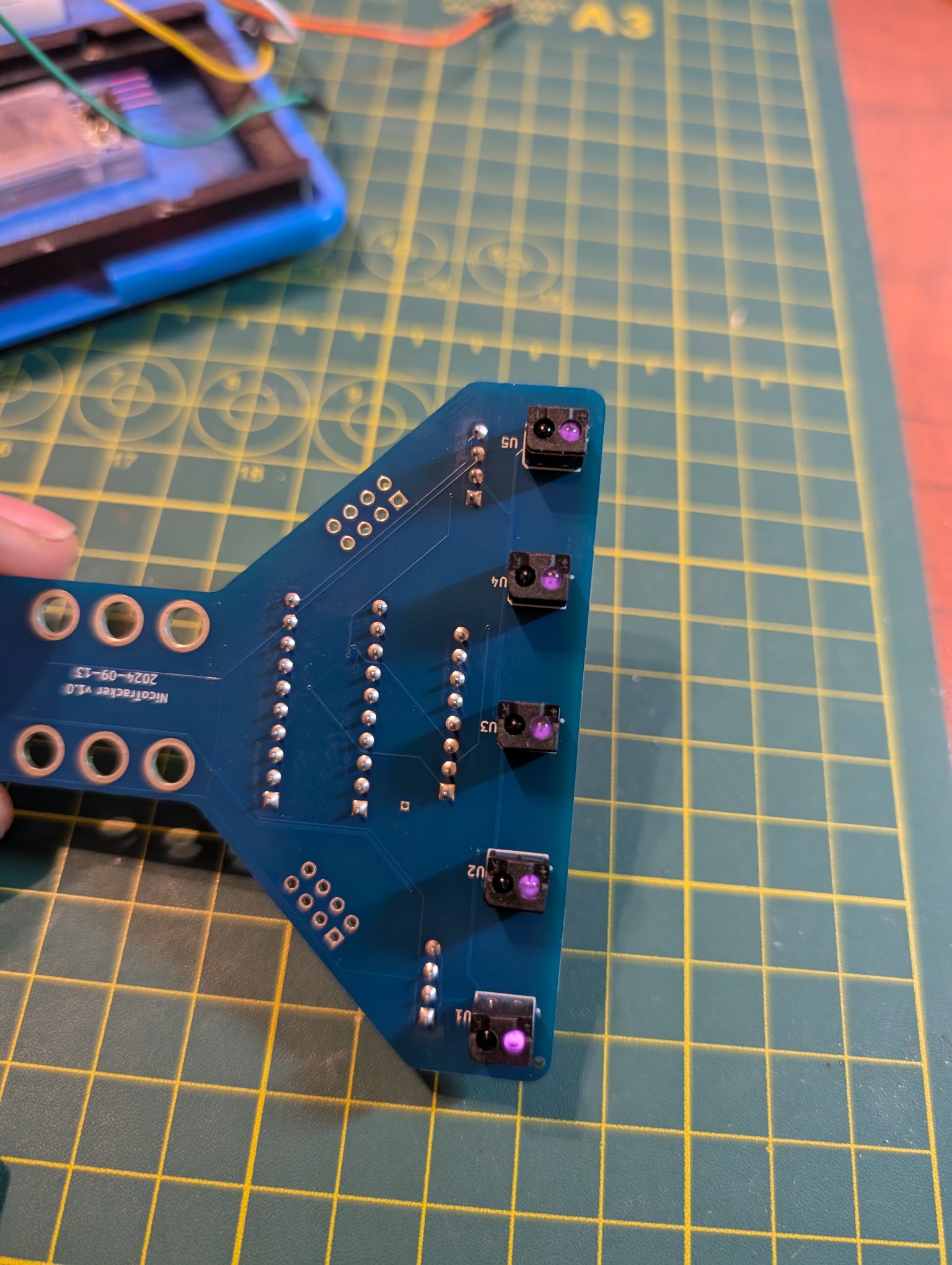
It is built around the ITR20001/T and SS14. Its parts include 11 resistors, 8 connectors, 5 ICs and 2 diodes. It belongs with the AVR (ATmega, ATtiny) boards of this library.
TODO : Add content to file... TODO : Add warning for the used RJ25 cable to jst connector
| Qty | Value | Footprint | References |
|---|---|---|---|
| 5 | 100 | easyeda2kicad:R0603 | R1, R3, R5, R7, R9 |
| 5 | 10K | easyeda2kicad:R0603 | R2, R4, R6, R8, R10 |
| 5 | ITR20001 | easyeda2kicad:OPTO-TH_DY-ITR20001 | U1, U2, U3, U4, U5 |
| 2 | Conn_01x04_Socket | Connector_PinSocket_2.54mm:PinSocket_1x04_P2.54mm_GVSCLSDC | J6, J7 |
| 2 | Conn_02x04_Counter_Clockwise | Connector_PinHeader_2.54mm:PinHeader_2x04_P2.54mm_Vertical | J1, J8 |
| 1 | 1K | easyeda2kicad:R0603 | R11 |
| 1 | ATtiny_L | Connector_PinSocket_2.54mm:PinSocket_1x10_P2.54mm_Vertical | J2 |
| 1 | ATtiny_R | Connector_PinSocket_2.54mm:PinSocket_1x10_P2.54mm_Vertical | J4 |
| 1 | Auriga_JST | Connector_JST:JST_XH_S6B-XH-A-1_1x06_P2.50mm_Horizontal | J5 |
| 1 | Conn_01x08_Socket | Connector_PinSocket_2.54mm:PinSocket_1x08_P2.54mm_Vertical | J3 |
| 1 | LED | LED_SMD:LED_0603_1608Metric | D2 |
| 1 | SS14 | easyeda2kicad:SMA_L4.2-W2.6-LS5.3-RD | D1 |
| 1 | TestPoint | Connector_PinHeader_1.00mm:PinHeader_1x01_P1.00mm_Vertical | TP1 |
| 1 | ~ | MountingHole:MountingHole_4.3mm_M4_Pad_TopBottom_MakeBlock | H1 |

yzxoi/stm32-ir-linescan-digit-recognizer
An STM32G0B1-based 8-channel infrared line-scan digit recognizer with custom KiCad hardware, USB-UART acquisition, Q15 preprocessing, and TinyML inference.

JGAguado/Smart_Plant
The Smart Plant is a board that can be plugged directly on the soil, close to the plant, that allows the measurement of the environment (soil moisture, environment temperature & illuminance), and presents the…

ugcs/ddc
Drone Show Software is software designed for drone shows, allowing flight path planning as well as control of dozens of drones simultaneously in a synchronized manner.

eddyem/stm32samples
Code samples and ready projects based on bare-metal STM32


execuc/u2if
USB to interfaces implementing MicroPython "machine" module functionalities on a computer.
It measures 85.6 × 78.2 mm and has 2 copper layers, 1.6 mm thick.
28 parts, built around the ITR20001/T and SS14. The full list of its parts is on this page, with links to each part's symbol and footprint where PCBKit's library has them.
From the nbourre/ATtiny1616WithLineTracker repository on GitHub, at the commit this page was made from: the board is ATtiny1616WithLineTracker.kicad_pcb and its schematic ATtiny1616WithLineTracker.kicad_sch. PCBKit opens the board in the browser, with nothing to install.
Its repository states no licence, so its author keeps all rights: ask nbourre before reusing the design.