4 layers100 × 80 mm
Open Beam Interface
nanographs/Open-Beam-Interface
Just what you need to control the beam and get an image.
334 parts371

 nanographs/Open-Beam-Interface371
Just what you need to control the beam and get an image.
Beam Offset Switch is an open-source printed circuit board by nanographs, from the nanographs/Open-Beam-Interface repository on GitHub. It is a 4-layer board of 50 × 42 mm with 46 parts on 31 nets, routed with 238 tracks and 186 vias.
Its parts include 10 resistors, 4 capacitors, 3 ICs, 3 connectors and 2 diodes.
Check out our docs at https://nanographs.github.io/Open-Beam-Interface/index.html
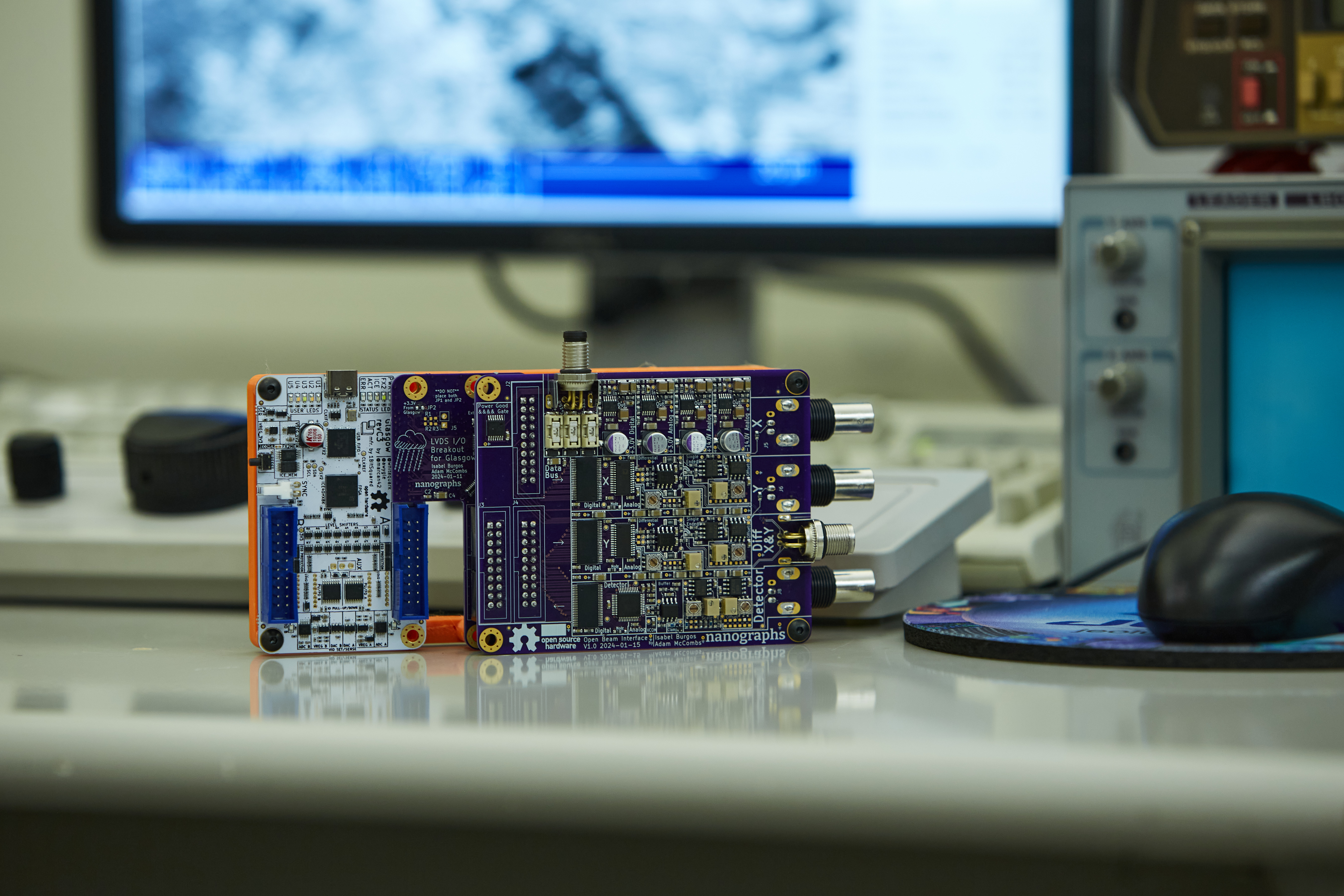
The Open Beam Interface project aims to make getting data into and out of scanning and patterning systems substantially more accessible. It is applicable to a variety of scanning and patterning systems but is especially useful for electron and ion microscopes.
Two high-speed digital-to-analog converters position the beam in X and Y and a high-speed analog-to-digital converter acquires the signal from a detector.
Just what you need to control the beam and get an image.
Built on Glasgow, written in Amaranth.
Glasgow makes getting bytes in and out of the FPGA over USB radically more accessible. We use that to make getting data into and out of your microscope radically more accessible.
Glasgow handles getting the bytes in and out of your computer. Our software takes those bytes and forms an image, while simultaneously streaming bytes to Glasgow to support raster and vector patterning applications.

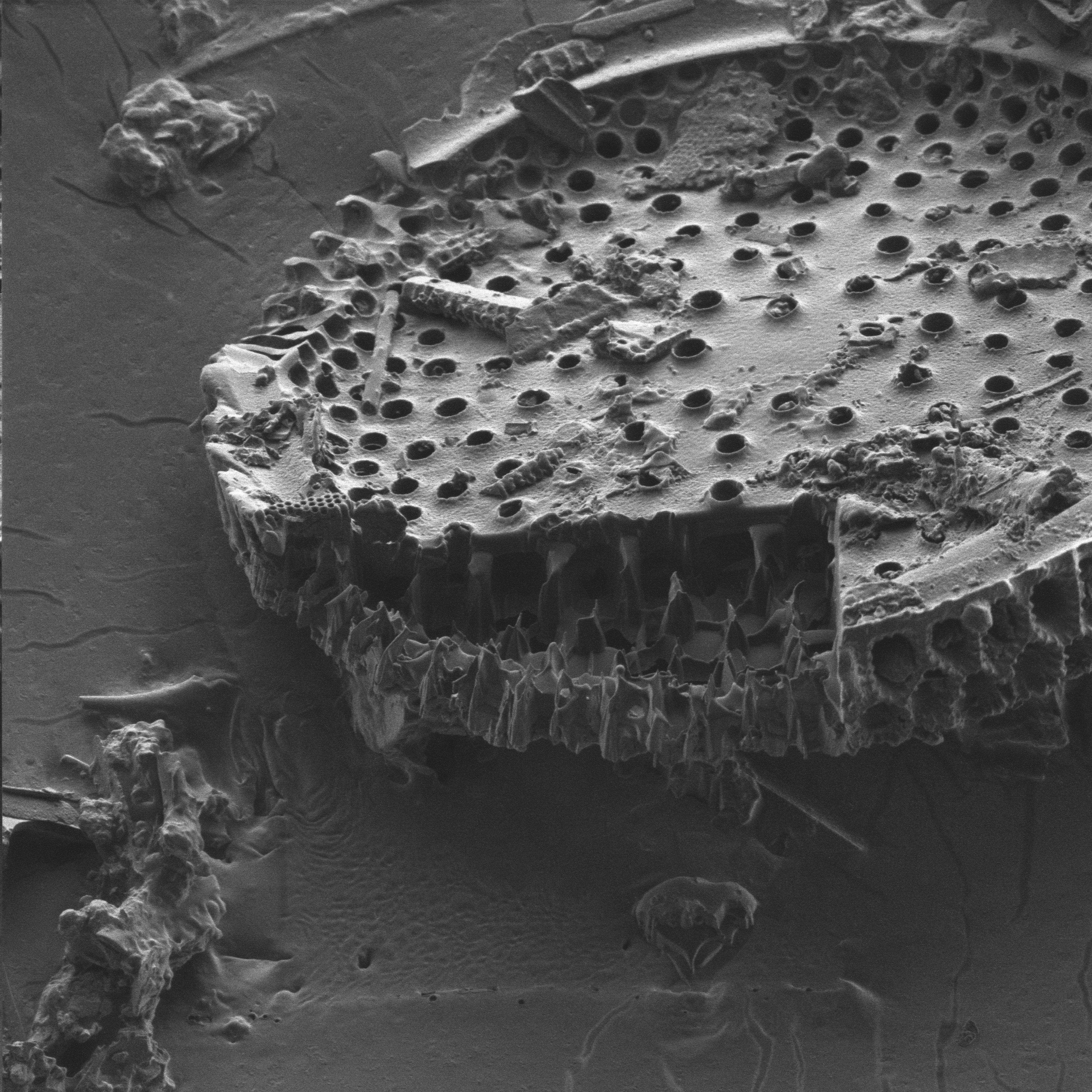
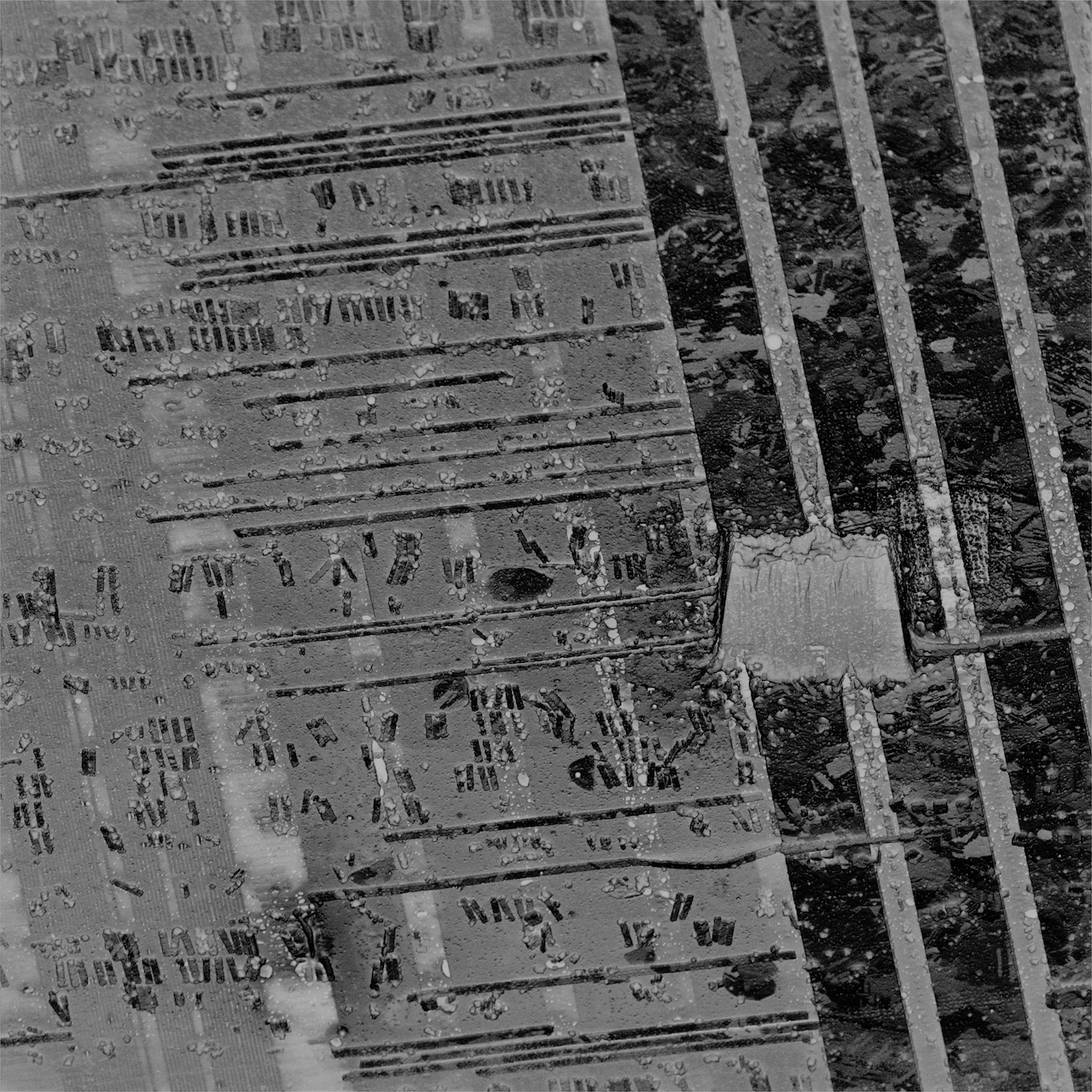
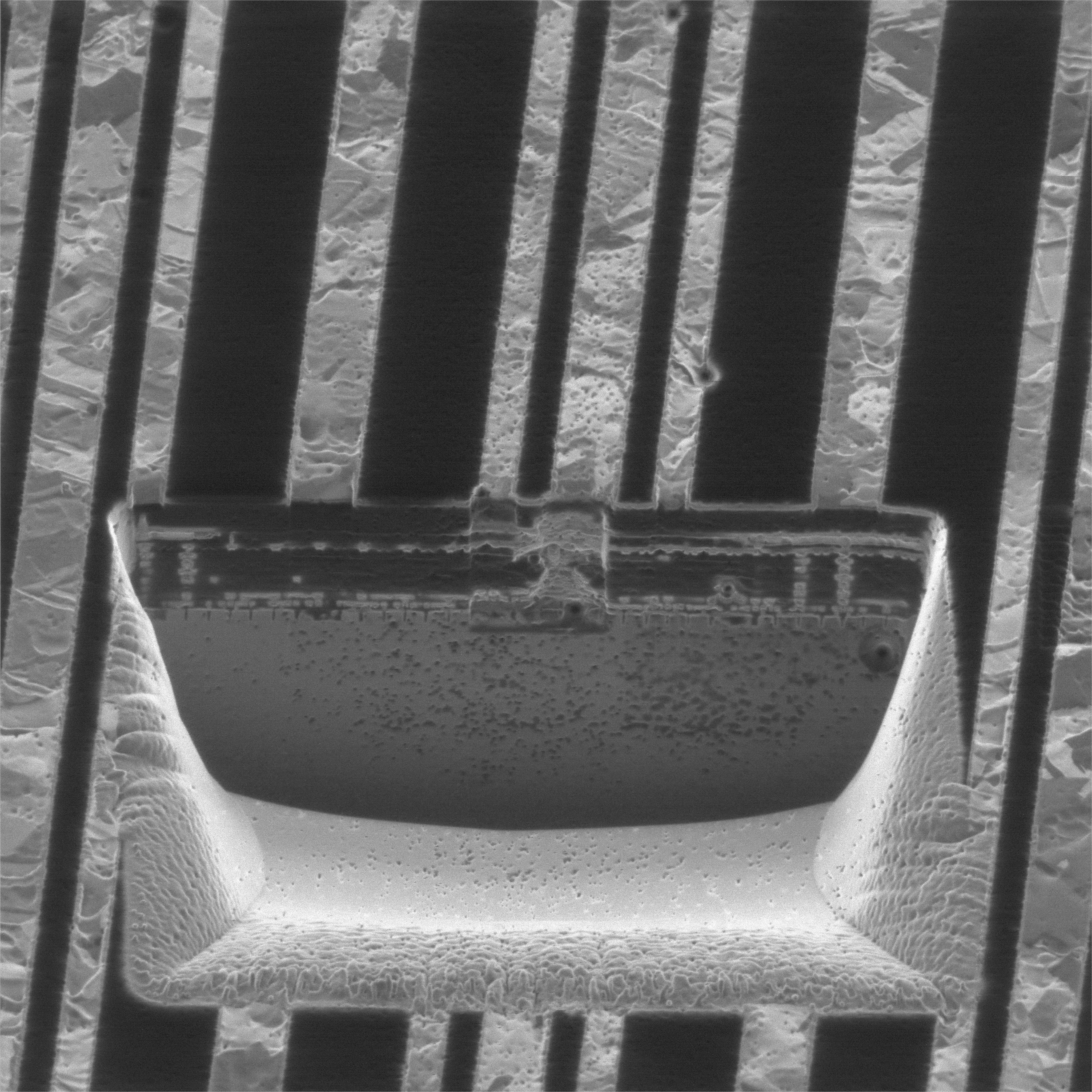
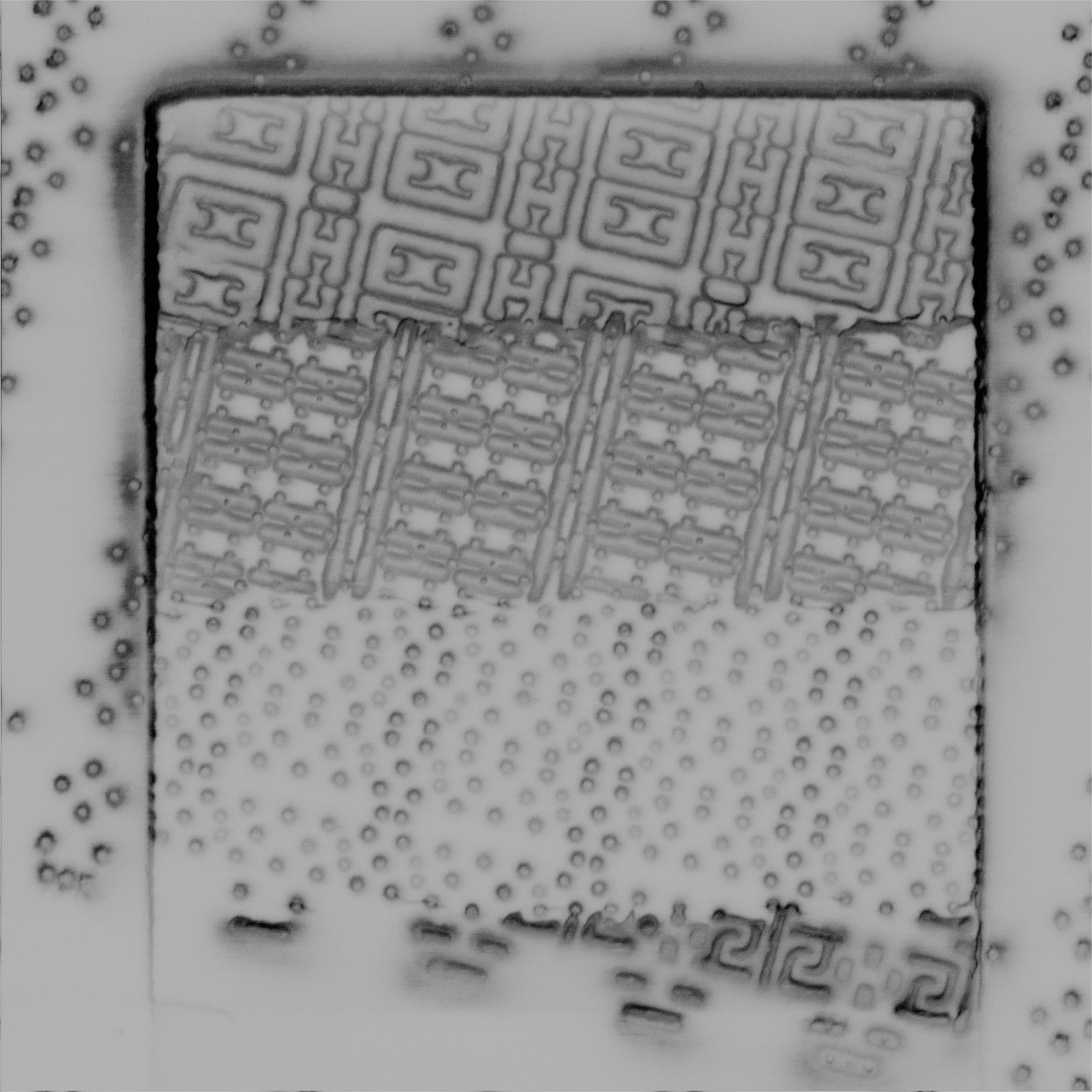
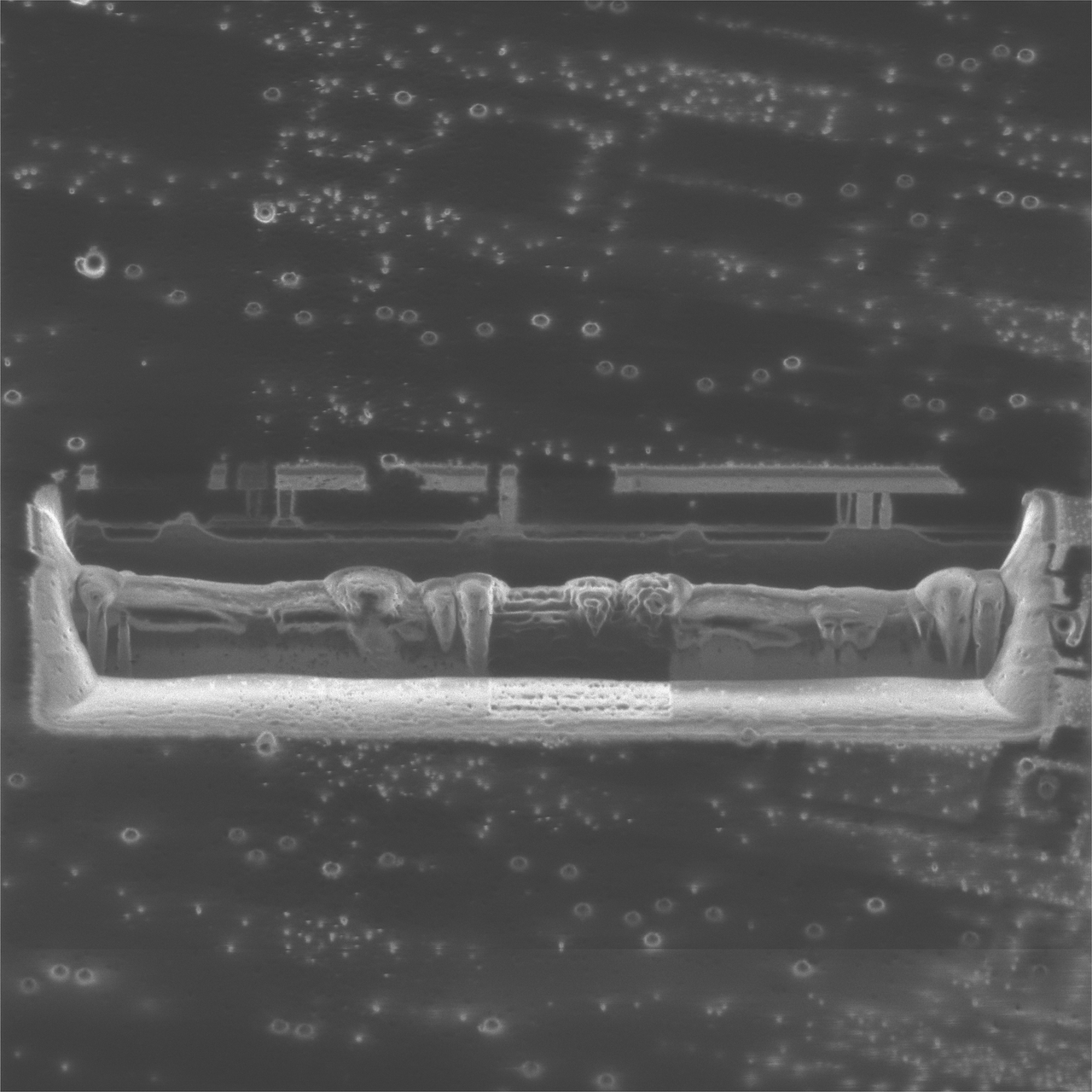
We have crafted this board to support as many microscopes as possible. We do not know of a SEM or FIB that specifically does not have these signals somewhere inside that can be tapped.
Many microscopes have an existing dedicated connector for external scan inputs. Originally, this was generally for external beam control coming from EDS or other X-Ray mapping systems.
For microscopes that do not have a dedicated external scan connector, the X and Y ramps that drive the scan coils exist somewhere. A relay can be installed to flip between internal and external scan. Sometimes, even when microscopes have a dedicated connector, it is better to tap the X and Y signals somewhere else.
Has a XY scan input that is either:
Has a video output that is:
Tapping into the signal path may require fabricating a custom cable.
Microscopes the board has been specifically integrated into, this is far from an exhaustive list of microscopes that we could interface with.
We would like to thank our sponsors' generous sustaining contributions. Without them, we would not be here today.
We are always open to potential microscope donations to use for hardware development, in order to expand the range of microscopes and capabilities we can support. Right now we are especially in search of FIBs, Dual Beams, and TEMs.
Thanks to the generous support of our financial sponsors, we have been able to dedicate almost all of our time and facility resources to developing the project this far. We are looking for more sponsors in order to continue our work, involve more engineers, and take this project to the next level.
Superior Technical Services
SEMion
CERN-OHL-W
| Qty | Value | Footprint | References |
|---|---|---|---|
| 11 | TestPoint | TestPoint:TestPoint_Pad_D1.0mm | TP1, TP2, TP3, TP4, TP5, TP6, TP7, TP8, TP9, TP10, TP11 |
| 6 | 500 | Resistor_SMD:R_0603_1608Metric | R5, R6, R7, R8, R9, R10 |
| 4 | 1k | Resistor_SMD:R_0603_1608Metric | R1, R2, R3, R4 |
| 4 | C | Capacitor_SMD:C_0603_1608Metric | C1, C2, C3, C4 |
| 4 | MountingHole | OBI Components:MountingHole_3.5mm_Pad_Via_CrtYd_CoperOverCorner | H1, H2, H3, H4 |
| 4 | R_Potentiometer_US | Potentiometer_SMD:Potentiometer_Bourns_3224W_Vertical | RV1, RV2, RV3, RV4 |
| 2 | Littel Fuse TVS Diode SMF20A | Diode_SMD:D_SMF | D1, D2 |
| 2 | RV1S9261A | OBI Components:LSSO5 | U2, U3 |
| 2 | ~ | OBI Components:Littel Fuse Holder 01550900M | FH1, FH2 |
| 1 | ADG5412_4x_SPST | Package_SO:TSSOP-16_4.4x5mm_P0.65mm | U1 |
| 1 | Conn_01x03 | Connector_PinSocket_2.54mm:PinSocket_1x03_P2.54mm_Vertical | J3 |
| 1 | Conn_01x04 | Connector_PinSocket_2.54mm:PinSocket_1x04_P2.54mm_Vertical | J2 |
| 1 | M8_conn_01x03_Pin_Shielded | OBI Connectors:M8_conn_01x03_Pin_Shielded_Right_Angle | J1 |
| 1 | TestPoint | TestPoint:TestPoint_THTPad_D1.0mm_Drill0.5mm | TP12 |
The 44 most common of 46 parts.
It measures 50 × 42 mm and has 4 copper layers, 1.57 mm thick.
46 parts. The full list of its parts is on this page, with links to each part's symbol and footprint where PCBKit's library has them.
From the nanographs/Open-Beam-Interface repository on GitHub, at the commit this page was made from: the board is Hardware/PCBs/Interface selectors and drivers/Beam Offset Switch/Beam Offset Switch.kicad_pcb and its schematic Hardware/PCBs/Data Interconnect/Data Interconnect revA1/OBI Data Interconnect.kicad_sch. PCBKit opens the board in the browser, with nothing to install.
Its repository states no licence, so its author keeps all rights: ask nanographs before reusing the design.
nanographs/Open-Beam-Interface
Just what you need to control the beam and get an image.

nanographs/Open-Beam-Interface
Just what you need to control the beam and get an image.

nanographs/Open-Beam-Interface
Just what you need to control the beam and get an image.

nanographs/Open-Beam-Interface
Just what you need to control the beam and get an image.

nanographs/Open-Beam-Interface
Just what you need to control the beam and get an image.

nanographs/Open-Beam-Interface
Just what you need to control the beam and get an image.

nanographs/Open-Beam-Interface
Just what you need to control the beam and get an image.

nanographs/Open-Beam-Interface
Just what you need to control the beam and get an image.

nanographs/Open-Beam-Interface
Just what you need to control the beam and get an image.

nanographs/Open-Beam-Interface
Just what you need to control the beam and get an image.


tomverbeure/fake_parallel_printer
Capture traffic on parallel printer port to USB

azonenberg/latentred
Open hardware 48x 1000baseT + 2x 25G SFP28 Ethernet switch


alvarop/chaac
This is a work in progress for a wireless weather station project.


fahreddinaykut/SparkAltBatteryBoard
A custom research-oriented battery interface and telemetry board for the DJI Spark platform, built around a standard 3S LiPo battery pack instead of the discontinued, hard-to-find OEM Smart Battery.