2 layers45.1 × 53.6 mm
Parallel2usb
tomverbeure/fake_parallel_printer
Capture traffic on parallel printer port to USB
44 parts95BSD-2-Clause

 tomverbeure/fake_parallel_printer95
Capture traffic on parallel printer port to USB
Parallel2usb is an open-source printed circuit board by tomverbeure, from the tomverbeure/fake_parallel_printer repository on GitHub, published under the BSD-2-Clause licence. It is a 4-layer board of 91.1 × 53.6 mm with 46 parts on 71 nets, routed with 443 tracks and 37 vias.
Its parts include 19 capacitors, 19 resistors, 3 connectors and 2 ICs. It belongs with the RP2040 boards of this library.
This repo contains the design files for the Fake Printer tool: a hardware dongle with a DB-25 connector that plugs into the parallel printer port that was available on nearly all computers and equipment in the eighties and nineties.
Check out this blog post for a detailed description of the design, and build and usage instructions:
There are 2 versions of the PCB. Revision 2 only uses 2 layers and doesn't stick out as much out of the device in which is plugged in. It's probably the best one to build. The firmware is designed to work for both PCB versions.
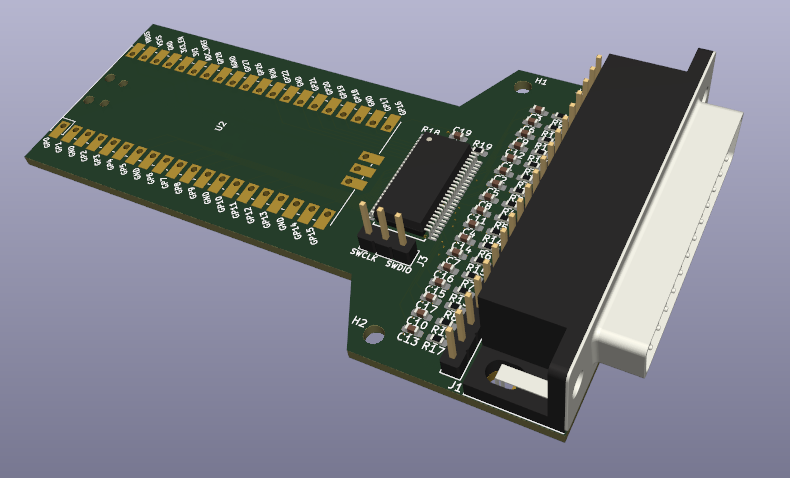
./parallel2usb_v1WARNING: v2 hasn't been tested!!!
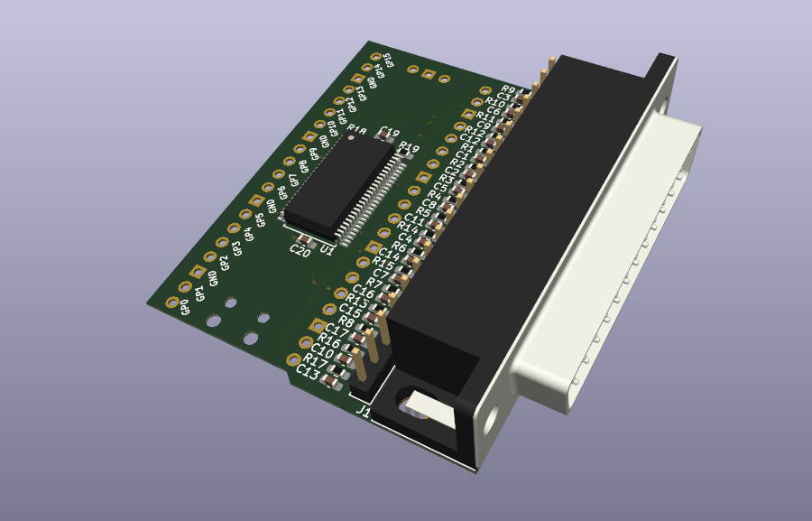
./parallel2usb_v2A Digikey cart with all the components to populate version 2 of the PCB can be found here. Not all resistors and capacitor must be populated though. Check out the blog post for details.
parallel2usb_hd_on.uf2 contains the compiled
firmware for the Raspberry Pico.
To make changes and recompile yourself:
set the PICO_SDK environment variable to the path of your locally installed
Raspberry Pico SDK.
Build the code:
mkdir -p ./c/build
cd ./c/build
cmake ..
make
If all goes well, a new parallel2usb.uf2 will be waiting in
./c/build/parallel2usb.
python3 ./fake_printer.py -p <USB serial device> (Use -h for more options.)PCL: use Ghostscript
~/tools/ghostpcl-10.0.0-linux-x86_64/gpcl6-1000-linux-x86_64 -dNOPAUSE -sOutputFile=output.png -sDEVICE=png256 -g8000x8000 -r600x600 print_cap.pcl
Epson ESC/P: use PrinterToPDF
/opt/printerToPDF/bin/printerToPDF -o output -f /opt/printerToPDF/lib/PrinterToPDF/font2/Epson-Standard.C16 print_cap.esc_p
Encapsulated Postscript: use Ghostscript and ImageMagick to add a background if necessary. Note that some scopes (TDS 684B) may emit a few chunks of comments that fake_printer.py will get with multiple-second delays, and they need to be concatenated together to form a valid eps file.
gs -dSAFER -dBATCH -dNOPAUSE -dEPSCrop -sDEVICE=pngalpha -r300 -sOutputFile=ph1-zoomout.png ph1-zoomout.eps; convert -background black -alpha remove -alpha off ph1-zoomout.png ph1-zoomout.png
./fake_printer.py --port=/dev/ttyACM0 -t 2 -v --prefix=hp_osc_ -s eps
inkscape -f ./hp_osc_0.eps -w 1580 -y=255 -e hp_osc_0.png
convert hp_osc_0.png -crop 1294x971+142+80 hp_osc_0_cropped.png
Advantest R3273
Config printer: Config -> Copy Config -> Printer:
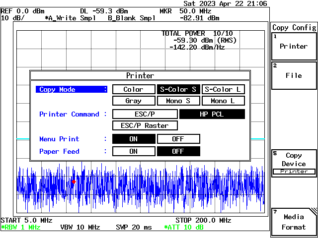
To print: Copy
To convert:
./fake_printer.py --port=/dev/ttyACM0 -t 2 -v --prefix=r3273_ -s pcl
~/tools/ghostpcl-10.0.0-linux-x86_64/gpcl6-1000-linux-x86_64 -dNOPAUSE -sOutputFile=test.png -sDEVICE=png256 -g8000x8000 -r600x600 r3273_0.pcl
convert test.png -filter point -resize 2000  test2.png
convert test2.png -crop 640x480+315+94 test3.png| Qty | Value | Footprint | References |
|---|---|---|---|
| 17 | 100p | Capacitor_SMD:C_0603_1608Metric_Pad1.08x0.95mm_HandSolder | C1, C2, C3, C4, C5, C6, C7, C8, C10, C11, C12, C13, C14, C15, C16, C17 +1 |
| 17 | 22 | Resistor_SMD:R_0603_1608Metric_Pad0.98x0.95mm_HandSolder | R1, R2, R3, R4, R5, R6, R7, R8, R10, R11, R12, R13, R14, R15, R16, R17 +1 |
| 2 | 4K7 | Resistor_SMD:R_0603_1608Metric_Pad0.98x0.95mm_HandSolder | R18, R19 |
| 2 | MountingHole | MountingHole:MountingHole_2.7mm_M2.5 | H1, H2 |
| 1 | 100n | Capacitor_SMD:C_0603_1608Metric_Pad1.08x0.95mm_HandSolder | C18 |
| 1 | 22u | Capacitor_SMD:C_0603_1608Metric_Pad1.08x0.95mm_HandSolder | C19 |
| 1 | 74LVC161284DL | Package_SO:SSOP-48_7.5x15.9mm_P0.635mm | U1 |
| 1 | Conn_01x03_Male | Connector_PinHeader_2.54mm:PinHeader_1x03_P2.54mm_Vertical | J3 |
| 1 | Conn_01x20 | Connector_PinHeader_2.54mm:PinHeader_1x20_P2.54mm_Vertical | J2 |
| 1 | DB25_Male_MountingHoles | Connector_Dsub:DSUB-25_Male_Horizontal_P2.77x2.84mm_EdgePinOffset7.70mm_Housed_MountingHolesOffset9.12mm | J1 |
| 1 | Pico | RPi_Pico:RPi_Pico_SMD_TH | U2 |
The 45 most common of 46 parts.
It measures 91.1 × 53.6 mm and has 4 copper layers, 1.61 mm thick.
46 parts. The full list of its parts is on this page, with links to each part's symbol and footprint where PCBKit's library has them.
From the tomverbeure/fake_parallel_printer repository on GitHub, at the commit this page was made from: the board is parallel2usb_v1/parallel2usb.kicad_pcb and its schematic parallel2usb_v1/KiCad-RP-Pico/Test/Test.kicad_sch. PCBKit opens the board in the browser, with nothing to install.
Its repository publishes it under the BSD-2-Clause licence: you may reuse it on that licence's terms (keep the author's notice, and for a copyleft licence share your changes alike).
tomverbeure/fake_parallel_printer
Capture traffic on parallel printer port to USB


nanographs/Open-Beam-Interface
Just what you need to control the beam and get an image.


azonenberg/latentred
Open hardware 48x 1000baseT + 2x 25G SFP28 Ethernet switch


alvarop/chaac
This is a work in progress for a wireless weather station project.


fahreddinaykut/SparkAltBatteryBoard
A custom research-oriented battery interface and telemetry board for the DJI Spark platform, built around a standard 3S LiPo battery pack instead of the discontinued, hard-to-find OEM Smart Battery.