2 layers65 × 80 mm
 nanjava82/headboard_hardware
KiCad에서 headerboard/headerboard.kicadpro를 열면 프로젝트를 사용할 수 있습니다. 기존 작업 환경은 KiCad 7.0.6입니다.
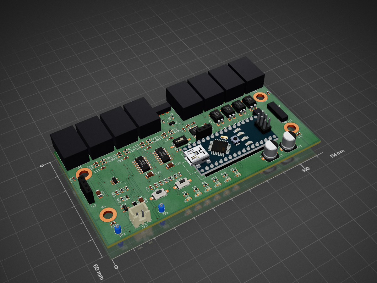
Headerboard is an open-source printed circuit board by nanjava82, from the nanjava82/headboard_hardware repository on GitHub. It is a 2-layer board of 114 × 60 mm with 110 parts on 114 nets, routed with 688 tracks and 139 vias.
It is built around the TLP521-4, 74HC14 and SN74LVC1G17DBVR, with the 35RAPC4BH3, SMBJ6.8CA and SMD1812P075TF among its other parts. Its parts include 34 resistors, 31 capacitors, 13 connectors, 11 diodes and 8 ICs. It belongs with the AVR (ATmega, ATtiny) boards of this library.


로드뷰 차량 4세대 헤더보드의 KiCad 설계 프로젝트입니다.
KiCad에서 headerboard/headerboard.kicad_pro를 열면 프로젝트를 사용할 수 있습니다. 기존 작업 환경은 KiCad 7.0.6입니다.
headerboard/headerboard.kicad_sch: 메인 회로도headerboard/headerboard.kicad_pcb: 현재 저장된 PCB 배치와 배선headerboard/headerboard.kicad_pro: 프로젝트 및 배선 규칙headerboard/: 보조 회로도, BOM·넷리스트 및 기존 STEP 출력물headerboard/gerber/, headerboard/gerber.zip: 기존 Gerber 및 드릴 출력물design/: 부품 심볼·풋프린트·3D 모델과 참고 자료첫 커밋은 2026-09-16 기준 디스크에 저장된 파일을 보존한 것입니다. Gerber·STEP·BOM은 폴더에 있던 출력물을 그대로 포함하며, 이번 커밋에서 다시 생성하지 않았습니다. 제작용 출력물은 해당 설계 버전과의 일치 여부를 확인해 사용합니다.
일부 사용자 라이브러리와 3D 모델은 기존 KiCad 환경의 경로 설정을 참조합니다. 다른 환경에서는 해당 라이브러리 및 모델 경로 설정이 필요할 수 있습니다. design/에 포함된 외부 부품 자료의 라이선스는 함께 있는 License.txt를 따릅니다.
자동 저장·백업·잠금 파일, 개인 화면 설정 및 routing-* 작업 폴더는 .gitignore로 제외합니다.
2026-09-16 추가 회로: 메인 회로도의 Buttons and OLED 하위 시트에 액티브 하이 버튼 2개와 OLED 4핀 소켓을 추가했습니다. 핀맵과 부품값, 회로도 PDF를 참고하세요.
2026-09-16 GNSS 출력 추가: GNSS 5V Pulse Output 하위 시트에 Arduino D10 기반 PwrPak7 MARK1용 보호 5V 출력을 추가했습니다. 핀맵·부품·케이블 및 펌웨어 설정, 전체 회로도 PDF를 참고하세요. 실물 검증은 아직 수행하지 않았습니다.
2026-09-16 PCB 배선: 사용자가 완료한 110개 부품 배치를 유지하고 UI·GNSS 출력을 포함해 배선했습니다. 미연결은 0개이며, 기존 배치·실크·라이브러리 DRC 항목은 남아 있습니다. 배선 미리보기와 검사 결과를 참고하세요.
| Qty | Value | Footprint | References |
|---|---|---|---|
| 8 | 35RAPC4BH3 | 35RAPC4BH3:SWITCHCRAFT_35RAPC4BH3 | J1, J2, J3, J4, J7, J8, J9, J10 |
| 8 | R_1608_220 | Resistor_SMD:R_0603_1608Metric | R13, R14, R15, R16, R22, R23, R24, R25 |
| 7 | C_1608_0.1uF | Capacitor_SMD:C_0603_1608Metric | C1, C3, C4, C5, C6, C18, C25 |
| 6 | 19-217_GHC-YR1S2_3T | Library_Matt:LED_0603_1608Metric | D2, D3, D5, D6, D7, D8 |
| 6 | R_1608_500 | Resistor_SMD:R_0603_1608Metric | R7, R8, R9, R10, R11, R12 |
| 4 | 100nF | Capacitor_SMD:C_0603_1608Metric | C26, C27, C28, C30 |
| 4 | C_1608_100NF_50V | Capacitor_SMD:C_0603_1608Metric | C16, C17, C19, C20 |
| 4 | C_1608_10nF | Capacitor_SMD:C_0603_1608Metric | C8, C9, C10, C11 |
| 4 | C_1608_1uF | Capacitor_SMD:C_0603_1608Metric | C12, C13, C14, C15 |
| 4 | C_3216_10uF | Capacitor_SMD:C_1206_3216Metric | C2, C22, C23, C24 |
| 4 | MountingHole_Pad_4.3mm | MountingHole:MountingHole_4.3mm_M4_DIN965_Pad | H1, H2, H3, H4 |
| 4 | R_1608_1k | Resistor_SMD:R_0603_1608Metric | R1, R2, R3, R4 |
| 4 | R_1608_20k | Resistor_SMD:R_0603_1608Metric | R18, R19, R20, R21 |
| 4 | TLP521 | Package_DIP:DIP-4_W7.62mm | U2, U3, U4, U5 |
| 3 | 10k | Resistor_SMD:R_0603_1608Metric | R28, R30, R34 |
| 3 | 1k | Resistor_SMD:R_0603_1608Metric | R27, R29, R31 |
| 2 | 10uF | Capacitor_SMD:C_1206_3216Metric | C29, C31 |
| 2 | 74HC14 | Package_SO:SOIC-14_3.9x8.7mm_P1.27mm | U6, U7 |
| 2 | C_6.3Ø _220UF_16V | Capacitor_SMD:CP_Elec_6.3x7.7 | C7, C21 |
| 2 | ITS-1163(SMD) | Headboard:SW_ITS1163_SMD | SW4, SW5 |
| 2 | R_1608_47 | Resistor_SMD:R_0603_1608Metric | R5, R6 |
| 2 | SMBJ6.8CA | Diode_SMD:D_SMB | D4, D9 |
| 2 | SMD1812P075 | Library_Matt:MSMD300 | F1, F2 |
| 2 | TestPoint | TestPoint:TestPoint_Loop_D1.80mm_Drill1.0mm_Beaded | TP1, TP2 |
| 1 | 180R / 0.5W | Resistor_SMD:R_1206_3216Metric | R33 |
| 1 | 47k | Resistor_SMD:R_0603_1608Metric | R32 |
| 1 | Arduino_Nano_v3.x | Module:Arduino_Nano | A1 |
| 1 | BAT54S | Package_TO_SOT_SMD:SOT-23 | D10 |
| 1 | GNSS_MARK1_5V | Connector_JST:JST_XH_B2B-XH-A_1x02_P2.50mm_Vertical | J13 |
| 1 | OLED_I2C_1x04 | Connector_PinSocket_2.54mm:PinSocket_1x04_P2.54mm_Vertical | J12 |
| 1 | PESD15VL2BT | Package_TO_SOT_SMD:SOT-23 | D1 |
| 1 | R_1608_10K | Resistor_SMD:R_0603_1608Metric | R26 |
| 1 | R_1608_10k | Resistor_SMD:R_0603_1608Metric | R17 |
| 1 | SMAW250-02 | Library_Matt:SMAW250-02 | J6 |
| 1 | SMW250-03 | Library_Matt:SMAW250-03 | J5 |
| 1 | SMW250-04 | Library_Matt:SMAW250-04 | J11 |
| 1 | SN74LVC1G17DBVR | Package_TO_SOT_SMD:SOT-23-5 | U8 |
| 1 | ST3232BTR | Package_SO:TSSOP-16_4.4x5mm_P0.65mm | U1 |
| 1 | SW_Push | Button_Switch_SMD:SW_DIP_SPSTx01_Slide_6.7x4.1mm_W8.61mm_P2.54mm_LowProfile | SW1 |
| 1 | SW_SPDT | Connector_PinSocket_2.54mm:PinSocket_1x03_P2.54mm_Vertical | SW2 |
| 1 | TPD1E10B06DYAR | Diode_SMD:D_SOD-523 | D11 |
It measures 114 × 60 mm and has 2 copper layers, 1.6 mm thick.
110 parts, built around the TLP521-4, 74HC14, SN74LVC1G17DBVR and 35RAPC4BH3. The full list of its parts is on this page, with links to each part's symbol and footprint where PCBKit's library has them.
From the nanjava82/headboard_hardware repository on GitHub, at the commit this page was made from: the board is headerboard/headerboard.kicad_pcb and its schematic headerboard/headerboard.kicad_sch. PCBKit opens the board in the browser, with nothing to install.
Its repository states no licence, so its author keeps all rights: ask nanjava82 before reusing the design.


aqualinkd/aqualinkd-zero-hat
Raspberry HAT to provide RS485 I/O and Power from Jandy RS485 control panel.

playduino/sheep-tester
Raspberry Pi 4B HAT for Playduino Sheep EOL factory test


Squantor/DiySolderingStation
Do it yourself soldering station

m24h/espcnc
A 3D printer/CNC controller using ESP32 with its DMA/FIFO bufferd I2S port