4 layers93.5 × 81 mm

 aqualinkd/aqualinkd-zero-hat6
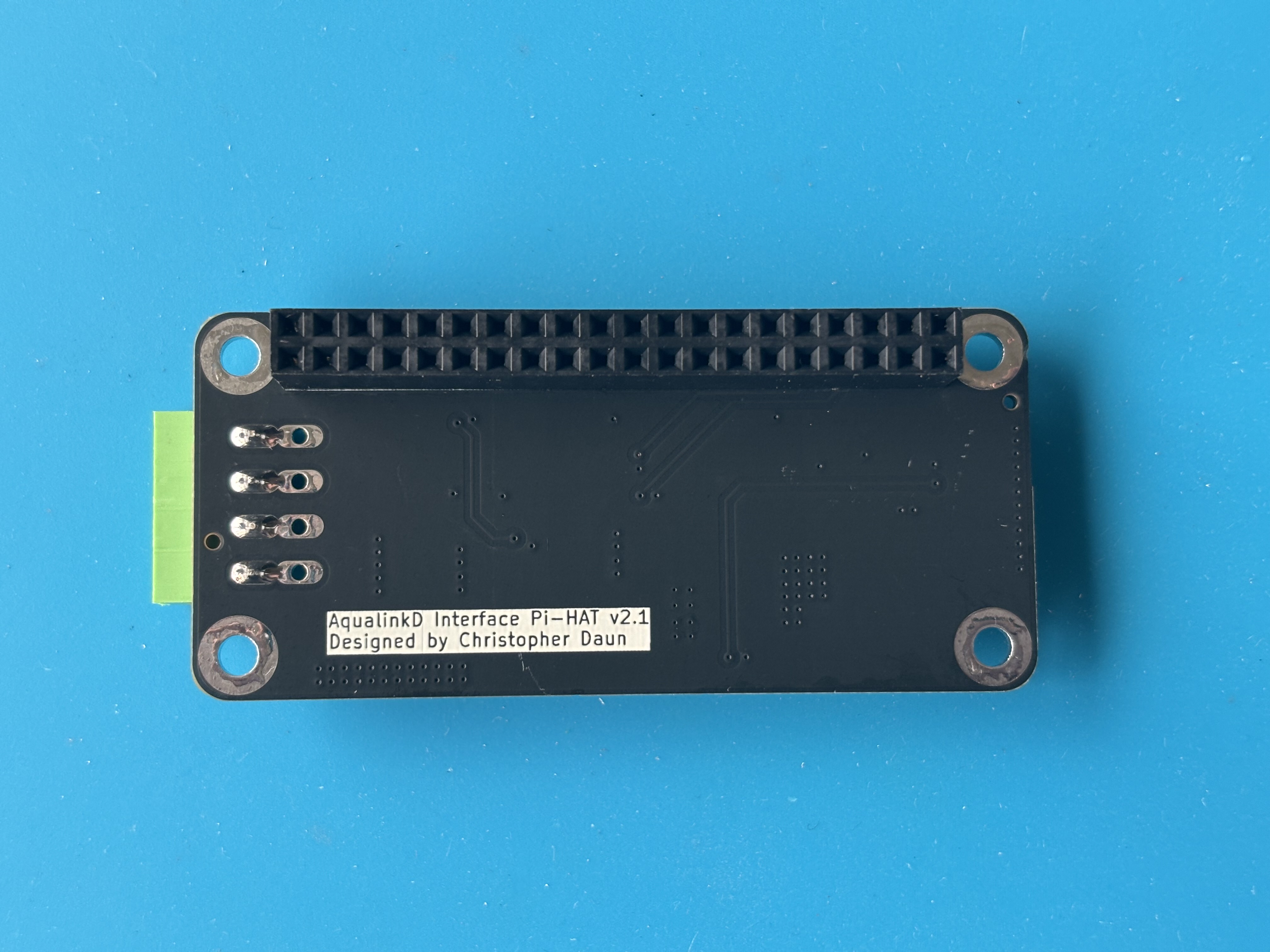
Raspberry HAT to provide RS485 I/O and Power from Jandy RS485 control panel.
Pi zero serial hat is an open-source printed circuit board by aqualinkd, from the aqualinkd/aqualinkd-zero-hat repository on GitHub. It is a 2-layer board of 65 × 30 mm with 45 parts on 54 nets, routed with 179 tracks and 89 vias.
It is built around the MAX13487EESA+, TPS5430DDA and MMBT5401, with the SMBJ6.8CA, AO3401A and B340 among its other parts. Its parts include 16 resistors, 8 capacitors, 7 diodes, 4 connectors and 3 transistors. It belongs with the interfaces and adapters boards of this library.


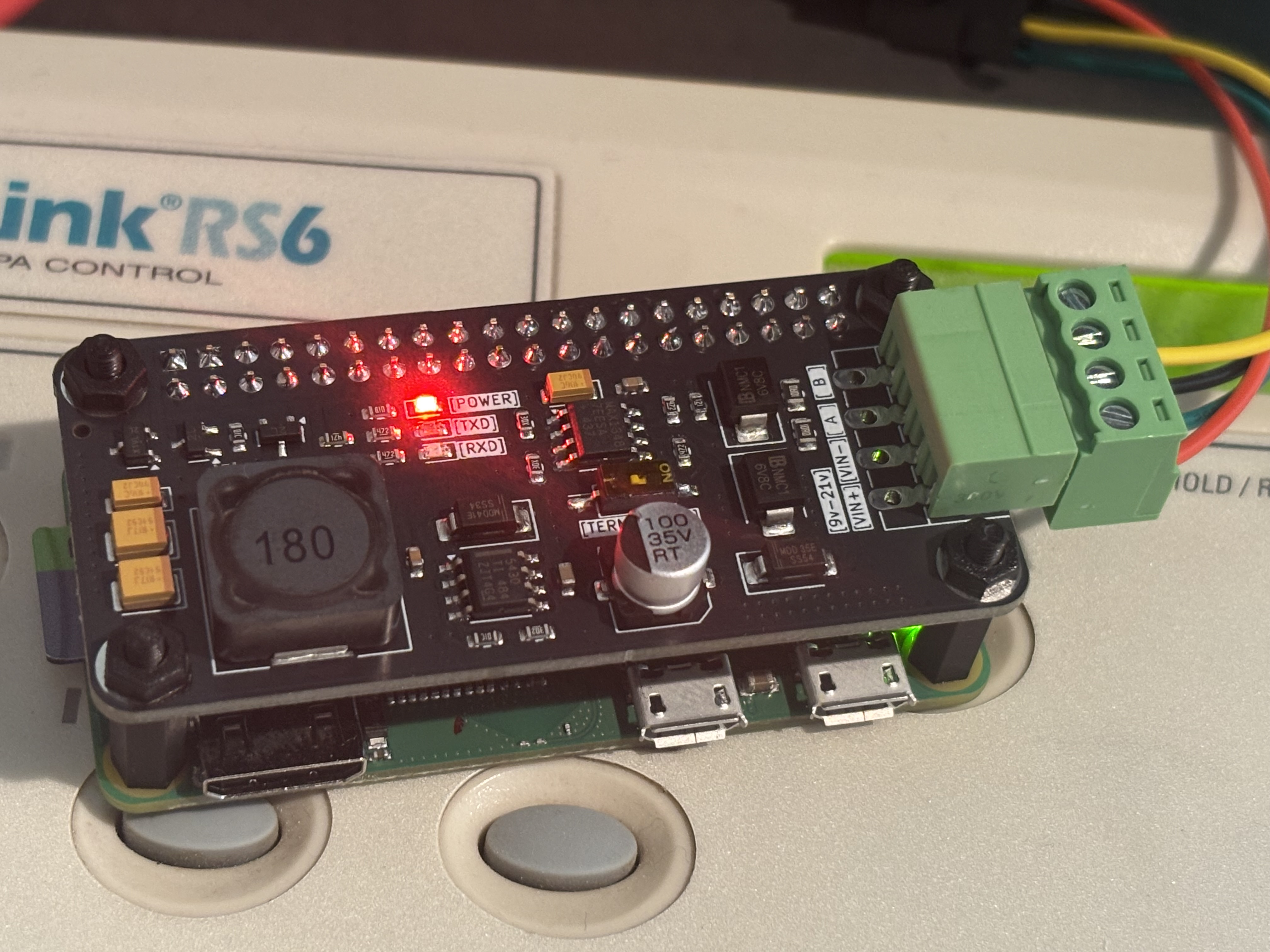
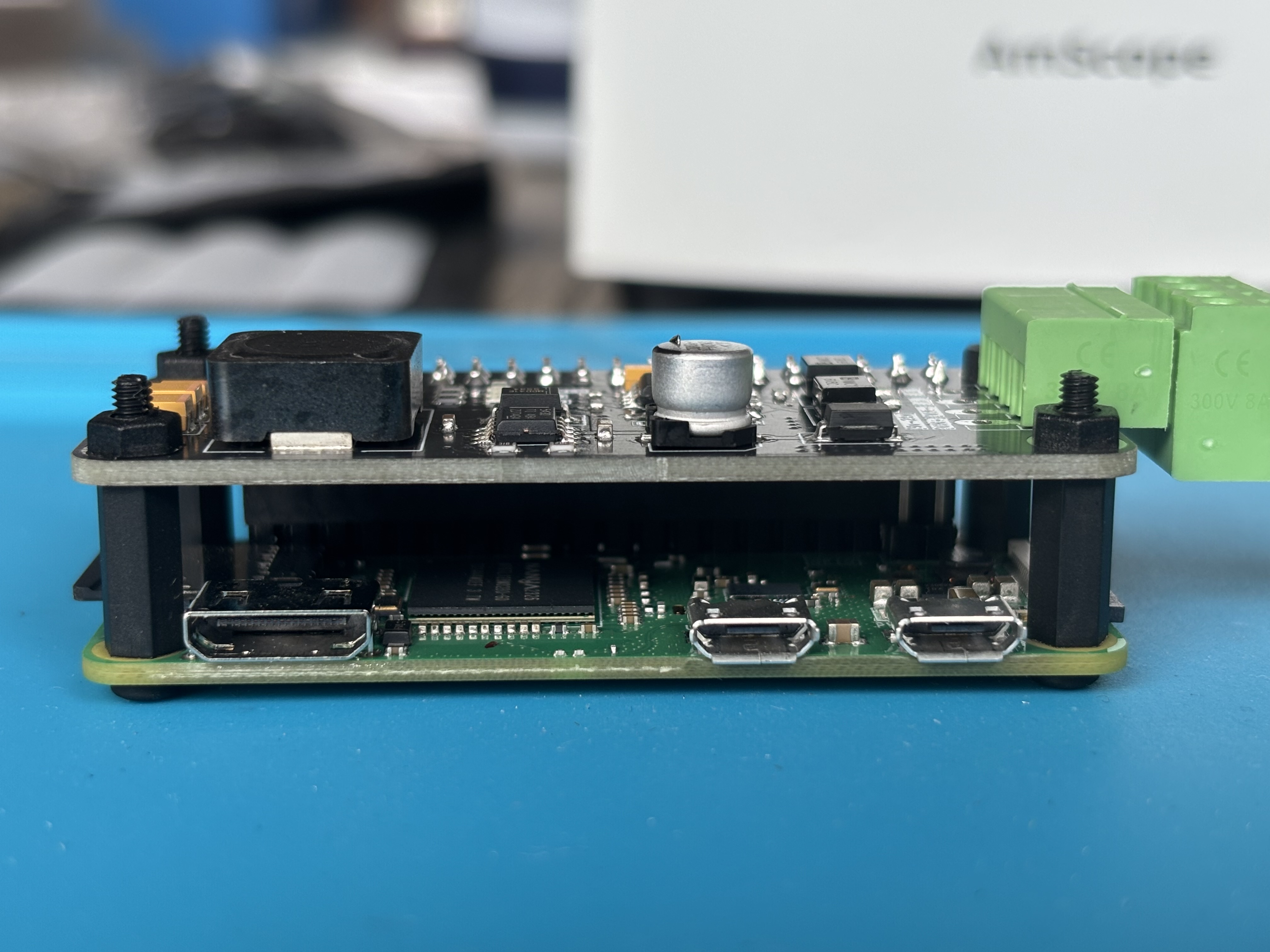
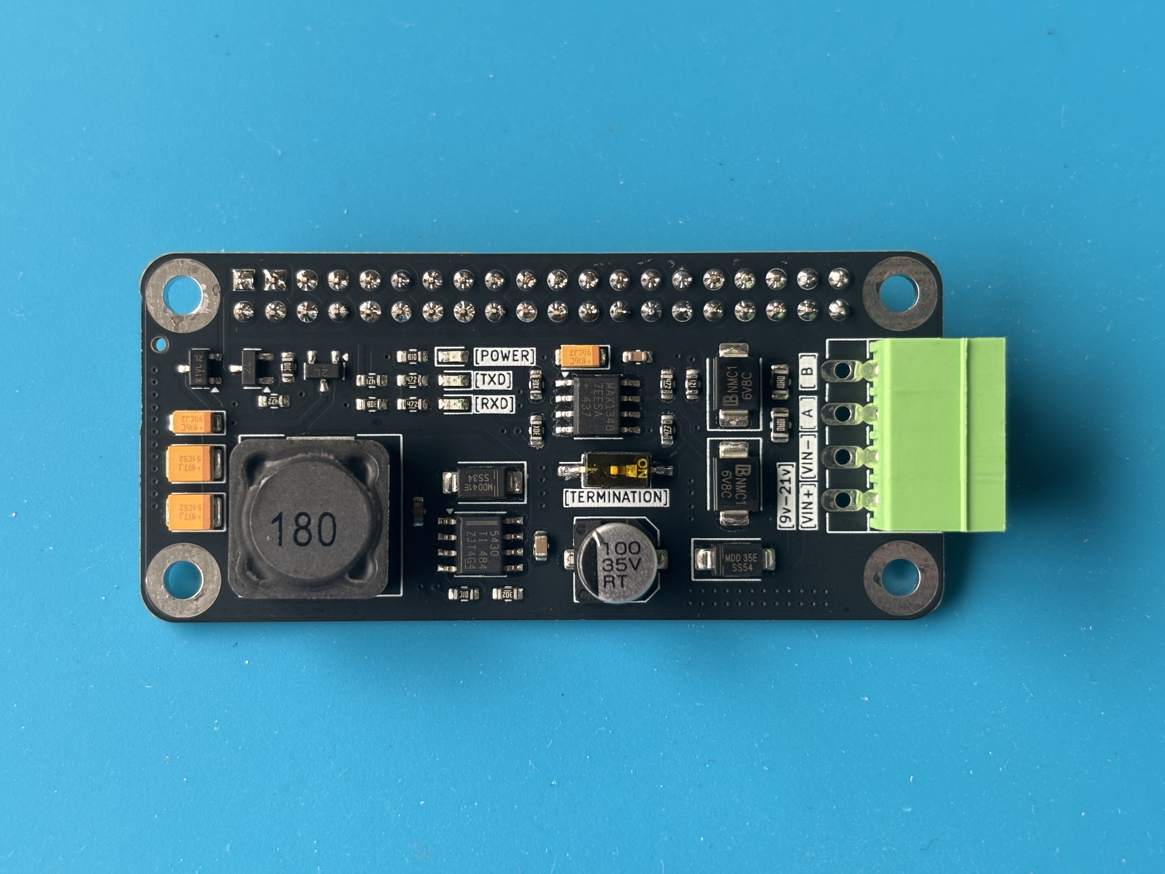
A Raspberry Pi HAT compatible with Raspberry Pi and similar SBCs
It is purpose built for use with AqualinkD and allows you to easily connect an SBC to the Aqualink Serial bus
sudo raspi-configInterface OptionsSerial PortNo when asked if you would like a login shell to be accessible over serial If you skip this step, aqualinkd will not workYes when asked if you would like the serial port hardware enabledOksudo vim /etc/aqualinkd.confserial_port=/dev/ttyS0rs485_frame_delay=10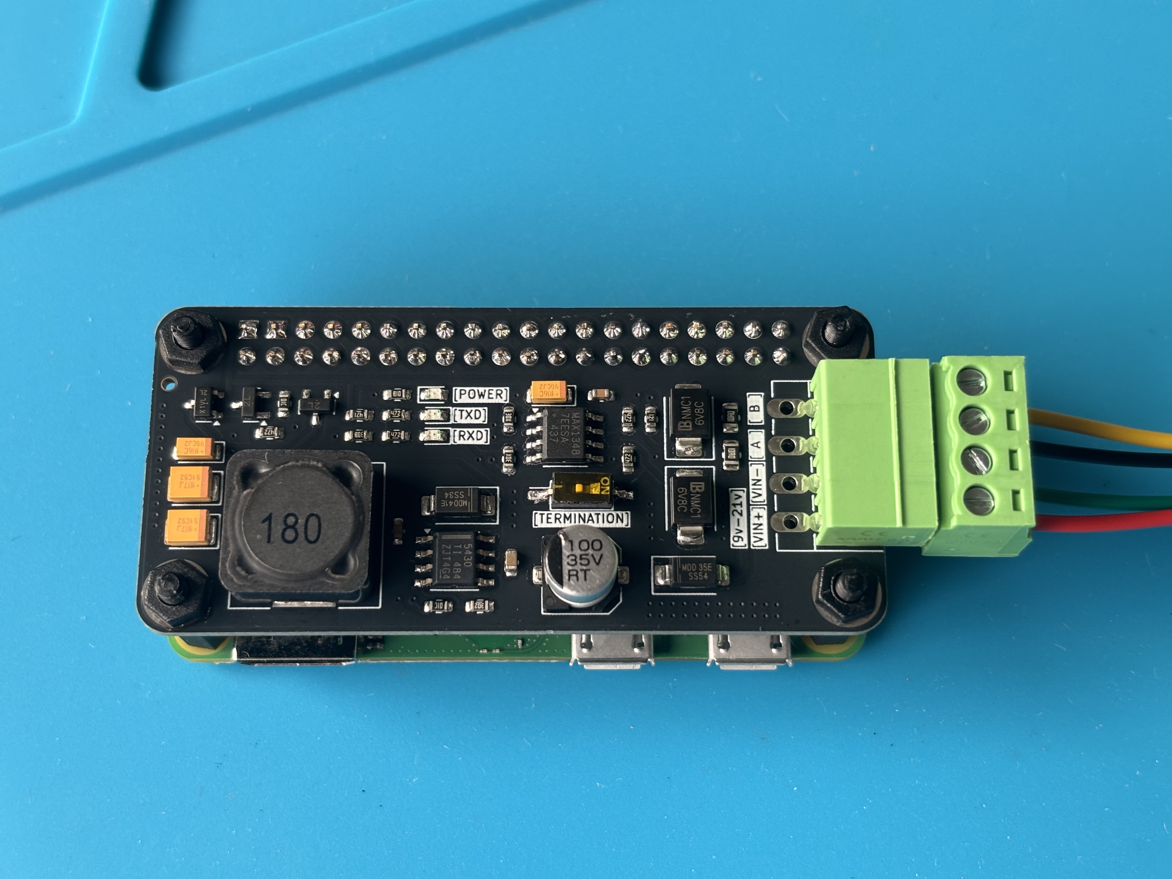
| Qty | Value | Footprint | References |
|---|---|---|---|
| 5 | 4.7kΩ | Resistor_SMD:R_0603_1608Metric | R1, R7, R9, R10, R13 |
| 4 | MountingHole_Pad | MountingHole:MountingHole_3mm_Pad | H1, H2, H3, H4 |
| 2 | 100uF | Capacitor_Tantalum_SMD:CP_EIA-3528-21_Kemet-B | C5, C6 |
| 2 | 10kΩ | Resistor_SMD:R_0603_1608Metric | R6, R14 |
| 2 | 10Ω | Resistor_SMD:R_0805_2012Metric | R3, R5 |
| 2 | 20Ω | Resistor_SMD:R_0603_1608Metric | R2, R8 |
| 2 | MMBT5401 | Package_TO_SOT_SMD:SOT-23 | Q2, Q3 |
| 2 | SMBJ6.8CA | Diode_SMD:D_SMB | D1, D2 |
| 2 | Screw_Terminal_01x04 | Connector_Phoenix_MC:PhoenixContact_MC_1,5_4-G-3.5_1x04_P3.50mm_Horizontal | J3, J4 |
| 1 | 100nF | Capacitor_SMD:C_0603_1608Metric | C2 |
| 1 | 100uF 35V | Capacitor_SMD:C_Elec_6.3x5.4 | C7 |
| 1 | 10nF | Capacitor_SMD:C_0603_1608Metric | C3 |
| 1 | 10uF | Capacitor_SMD:C_0603_1608Metric | C8 |
| 1 | 10uF | Capacitor_Tantalum_SMD:CP_EIA-3216-18_Kemet-A | C1 |
| 1 | 10uf | Capacitor_Tantalum_SMD:CP_EIA-3216-18_Kemet-A | C4 |
| 1 | 120Ω | Resistor_SMD:R_0603_1608Metric | R4 |
| 1 | 18uH | Inductor_SMD:L_Sunlord_SWRB1204S | L1 |
| 1 | 1kΩ | Resistor_SMD:R_0603_1608Metric | R16 |
| 1 | 2kΩ | Resistor_SMD:R_0603_1608Metric | R12 |
| 1 | 3kΩ | Resistor_SMD:R_0603_1608Metric | R15 |
| 1 | 470Ω | Resistor_SMD:R_0603_1608Metric | R11 |
| 1 | AO3401A | Package_TO_SOT_SMD:SOT-23 | Q1 |
| 1 | B340 | Diode_SMD:D_SMA | D5 |
| 1 | Conn_02x20_Counter_Clockwise | lib:PinSocket_2x20_P2.54mm_Vertical_Centered_Anchor | J1 |
| 1 | D | Diode_SMD:D_SMA | D7 |
| 1 | LED | LED_SMD:LED_0603_1608Metric | D6 |
| 1 | LED_RXD | LED_SMD:LED_0603_1608Metric | D4 |
| 1 | LED_TXD | LED_SMD:LED_0603_1608Metric | D3 |
| 1 | MAX13487EESA+ | Package_SO:SOIC-8_3.9x4.9mm_P1.27mm | U1 |
| 1 | SW_DIP_x01 | Button_Switch_SMD:SW_DIP_SPSTx01_Slide_Copal_CHS-01B_W7.62mm_P1.27mm | J2 |
| 1 | TPS5430DDA | Package_SO:TI_SO-PowerPAD-8_ThermalVias | U2 |
It measures 65 × 30 mm and has 2 copper layers, 1.6 mm thick.
45 parts, built around the MAX13487EESA+, TPS5430DDA, MMBT5401 and SMBJ6.8CA. The full list of its parts is on this page, with links to each part's symbol and footprint where PCBKit's library has them.
From the aqualinkd/aqualinkd-zero-hat repository on GitHub, at the commit this page was made from: the board is KiCAD/pi-zero-serial-hat.kicad_pcb and its schematic KiCAD/pi-zero-serial-hat.kicad_sch. PCBKit opens the board in the browser, with nothing to install.
Its repository states no licence, so its author keeps all rights: ask aqualinkd before reusing the design.

playduino/sheep-tester
Raspberry Pi 4B HAT for Playduino Sheep EOL factory test

8aChristian/InduLink-485
The board follows rigorous IPC (IPC-2152, IPC-2221, IPC-7351) standards, complete with galvanic isolation, industrial transient protection (TVS, Schottky, PTC Polyfuse), a wide-input step-down switching power…

N5GEH/n5geh.devices.iot_wa_dio-
IoT-DIO is a wireless adapter for developing IoT applications for Industrial and Building Automation Systems based on the Espressif chipset ESP32. The adapter is compatible with: - RS485 - M-Bus - Ethernet

nanjava82/headboard_hardware
KiCad에서 headerboard/headerboard.kicadpro를 열면 프로젝트를 사용할 수 있습니다. 기존 작업 환경은 KiCad 7.0.6입니다.

freeDSP/freeDSP-OCTAVIA
8ch Output ADAU1452/1466 DSP Board with Analog/COAX/OPT/USB/Raspberry-Pi Input

Skrooter/PI-DMX-hat
A DMX hat for Raspberry pi which can also be used to power a Pi from 12V

kikiosvetnik/rpm-meter-with-atmel168
PCB and Software project of RPM meter using atmega168 and custom pcb