
2 layers200 × 164.9 mm
Order4 notent
nEDM-TUM/Temperature-Sensor-System
System for reading/writing temperature sensors
306 parts
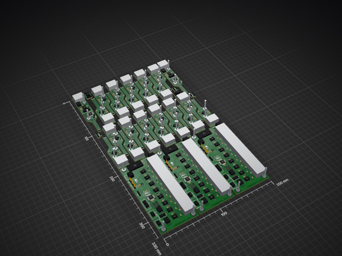
System for reading/writing temperature sensors
NewOrder is an open-source printed circuit board by nEDM-TUM, from the nEDM-TUM/Temperature-Sensor-System repository on GitHub. It is a 2-layer board of 200 × 330 mm with 658 parts on 72 nets, routed with 6,289 tracks and 300 vias.
It is built around the ATMEGA88A-AU, LM7805 and RJ45, with the SO8 among its other parts. Its parts include 210 resistors, 200 capacitors, 82 ICs, 71 connectors and 19 diodes. It belongs with the sensors and measurement boards and the AVR (ATmega, ATtiny) boards of this library.


Sensor network system built for the nEDM experiment.
.
+-- casings     // 3D CAD files for 3D printer
|   +-- adapter
|   +-- arduino
|   +-- cable_clamp
|   +-- collector
|   +-- humidity
|   +-- temperature
+-- circuit_boards      // Circuit schematic diagram and
|   |                   // PCB schematic files created using KiCad
|   +-- 3x127_254_adapter       // A PCB chip adapter,
|   |                           // used for breadboard debugging
|   +-- 4x127_254_adapter       // A PCB chip adapter,
|   |                           // used for breadboard debugging
|   +-- arduino_adapter
|   +-- humidity
|   +-- kicad_library           // Footprint and Component
|   |                           // library files for KiCad
|   +-- order           // PCB assembly, which was sent to
|   |                   // Fischer Leiterplatten for production
|   +-- sensor_board
|   +-- so8_breakout    // A PCB chip adapter,
|   |                   // used for breadboard debugging
| +-- temperature_board###For more details about our project, please read the report document. ### Its tex file and needed images can be found in the folder report. You can use make to compile the document.
| Qty | Value | Footprint | References |
|---|---|---|---|
| 98 | 22k | SM0603_big | R10, R10, R10, R11, R11, R11, R12, R12, R12, R13, R13, R13, R14, R14, R14, R15 +82 |
| 80 | 100nF | SM0603_big | C1, C1, C1, C1, C1, C1, C1, C1, C1, C1, C1, C1, C1, C1, C1, C1 +64 |
| 75 | 100n | SM0603_big | C10, C10, C10, C11, C11, C11, C12, C12, C12, C13, C13, C13, C14, C14, C14, C15 +59 |
| 59 | VAL** | m3_loch | m3_loch, m3_loch, m3_loch, m3_loch, m3_loch, m3_loch, m3_loch, m3_loch, m3_loch, m3_loch, m3_loch, m3_loch, m3_loch, m3_loch, m3_loch, m3_loch +43 |
| 49 | 120 | SM0603_big | R18, R18, R18, R19, R19, R19, R20, R20, R20, R21, R21, R21, R30, R30, R30, R31 +33 |
| 49 | ST485 | st485 | U1, U1, U2, U2, U2, U2, U2, U2, U2, U2, U2, U2, U2, U2, U2, U2 +33 |
| 27 | 10uF | SM0805_big | C2, C2, C3, C3, C3, C3, C3, C3, C3, C3, C3, C3, C3, C3, C3, C3 +11 |
| 25 | RJ45 | RJ45_8P8_simple | J1, J1, J1, J1, J1, J1, J1, J1, J1, J1, J1, J1, J1, J1, J1, J1 +9 |
| 23 | 220 | SM0603_big | R1, R1, R1, R1, R1, R1, R1, R1, R1, R1, R1, R1, R1, R1, R1, R1 +7 |
| 23 | TSIC50XF | Tsic_TO92 | U1, U1, U1, U1, U1, U1, U1, U1, U1, U1, U1, U1, U1, U1, U1, U1 +7 |
| 19 | 150 | SM0805_big | R1, R1, R2, R2, R2, R2, R2, R3, R3, R3, R4, R4, R4, R5, R5, R5 +3 |
| 10 | 2k2 | SM0603_big | R6, R6, R6, R7, R7, R7, R7, R7, R8, R8 |
| 9 | 10u | SM0805_big | C1, C1, C1, C23, C23, C23, C24, C24, C24 |
| 8 | 10k | SM0603_big | R1, R1, R1, R3, R3, R9, R9, R9 |
| 7 | CONN_4 | Stiftleiste_4x1 | P1, P1, P2, P2, P2, P3, P3 |
| 6 | 22p | SM0603_big | C3, C3, C3, C4, C4, C4 |
| 5 | ISP | wannenstecker_2x5_rm254 | P1, P1, P8, P8, P8 |
| 5 | SW_RESET | Taster_6mm | SW1, SW1, SW3, SW3, SW3 |
| 5 | UART | Stiftleiste_4x1 | P1, P1, P1, P2, P2 |
| 4 | LED | SM0603_big | D1, D1, D2, D2 |
| 3 | 0 | SM0805_big | R34, R34, R34 |
| 3 | 12Vin | LPV_Stiftleiste_2pol | P5, P5, P5 |
| 3 | 20MHz | HC-49_quarz_big | X1, X1, X1 |
| 3 | 330nF | SM0603_big | C5, C5, C5 |
| 3 | 5Vin | LPV_Stiftleiste_2pol | P9, P9, P9 |
| 3 | ATMEGA88A-A | TQFP32 | IC1, IC1, IC1 |
| 3 | CONN_4 | HYT271 | P1, P1, P1 |
| 3 | HOHLBUCHSE | hohlbuchse_475_17 | P6, P6, P6 |
| 3 | LED1 | SM0603_big | D1, D1, D1 |
| 3 | LED2 | SM0603_big | D2, D2, D2 |
| 3 | LED3 | SM0603_big | D3, D3, D3 |
| 3 | LED4 | SM0603_big | D4, D4, D4 |
| 3 | LED_POW | SM0603_big | D5, D5, D5 |
| 3 | LM7805 | lm7805_lying | U1, U1, U1 |
| 3 | RJ45_8P8C_8FACH | RJ45_8P8C_8x | J1, J1, J1 |
| 3 | SCHALTER_2POL | DIP_Schalter_2pol | SW2, SW2, SW2 |
| 3 | SW1 | Taster_6mm | SW1, SW1, SW1 |
| 3 | Shield | m3_scheibe | P2, P2, P2 |
| 3 | Vccin | LPV_Stiftleiste_2pol | P7, P7, P7 |
| 3 | i2c_chain | wannenstecker_2x3_rm254 | P4, P4, P4 |
| 3 | i2c_pow | wannenstecker_2x3_rm254 | P3, P3, P3 |
| 3 | pow_sel | Stiftleiste_3x1 | K1, K1, K1 |
| 2 | ATMEGA88-A | TQFP32 | IC1, IC1 |
| 2 | HYT271 | HYT271 | U2, U2 |
| 2 | so8 | st485 | P2, P2 |
nEDM-TUM/Temperature-Sensor-System
System for reading/writing temperature sensors

nEDM-TUM/Temperature-Sensor-System
System for reading/writing temperature sensors

nEDM-TUM/Temperature-Sensor-System
System for reading/writing temperature sensors

nEDM-TUM/Temperature-Sensor-System
System for reading/writing temperature sensors

nEDM-TUM/Temperature-Sensor-System
System for reading/writing temperature sensors


nEDM-TUM/Temperature-Sensor-System
System for reading/writing temperature sensors

nEDM-TUM/Temperature-Sensor-System
System for reading/writing temperature sensors

klaus-liebler/sensact
Es gibt vier Namespaces für Nachrichten "REQUEST" und "RESPONSE", "EVENT" und "ACKNOWLEDGE". Dies wird mit den beiden LSB des Versions-Namespace-Bytes erklärt (Somit bleiben 64 Versionierungsmöglichkeiten) Alle vier…


DavidMFlynn/VideoSelector
Sets camera to monitor connections, RS-232, Extron Electronics MAV 88, PIC16F1847.


It measures 200 × 330 mm and has 2 copper layers, 1.6 mm thick.
658 parts, built around the ATMEGA88A-AU, LM7805, RJ45 and SO8. The full list of its parts is on this page, with links to each part's symbol and footprint where PCBKit's library has them.
From the nEDM-TUM/Temperature-Sensor-System repository on GitHub, at the commit this page was made from: the board is circuit_boards/order/newOrder.kicad_pcb. PCBKit opens the board in the browser, with nothing to install.
Its repository states no licence, so its author keeps all rights: ask nEDM-TUM before reusing the design.