2 layers65 × 56 mm
 myRaspberryPiArticles/Autopilot-Hackpad
This is my HackPad/MacroPad project for the blueprint scheme for Hack Club! I have designed this to work with my MSFS 2024 to make autopilot configuration easier and more immersive.
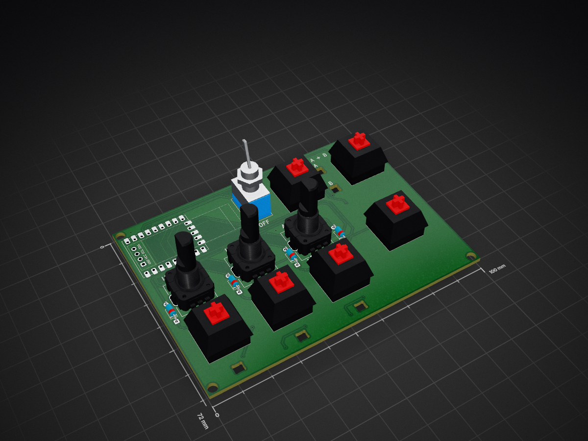
MacroPadAutopilot is an open-source printed circuit board by myRaspberryPiArticles, from the myRaspberryPiArticles/Autopilot-Hackpad repository on GitHub. It is a 2-layer board of 100 × 72 mm with 23 parts on 28 nets, routed with 332 tracks and 13 vias.
It belongs with the keyboards and input boards of this library.
This is my HackPad project for the Hack Club Blueprint YSWS! I have designed this to work with my flight simulator to make autopilot configuration easier and more immersive.
Notes for reviewers
- As TinkerCAD does not support STEP files, I have provided STL files and the link to my design, so you can export it into different softwares if you wish!
- My design uses some custom parts not provided by Blueprint - I will buy and source these parts myself! We have confirmed this on Slack!
PCB view:
Schematic view:
Here are the two parts of the case, the top section and the bottom bumper-style part: You can find my Tinkercad design here: https://www.tinkercad.com/things/kMuqWNtUm2q/edit?returnTo=%2Fthings&sharecode=TvnqmuXe9pAtwGBK2sJ9aHeb2CSNASbWhCyXTYQ4DW4
3D visualization of the PCB
3D visualization of the final HackPad - It is my attempt at Fusion360 but you will find the case in the Case folder from Tinkercad
I will assemble it by soldering on all the parts on the top, except the RP2040 Zero which will be upside down, and then snug fit it inside the bottom part of the case. Then, I will put the top part of the case on top and use 4 M3x16mm screws to put it all in place. After that, I might put some sticky rubber spots on the bottom to give it extra grip after it is all in place!
| Part | Quantity | Purpose |
|---|---|---|
| MX_SK6812MINI-E | 5 | LEDs |
| D_DO-35_SOD27_P7.62mm_Horizontal | 6 | Diodes |
| SW_Cherry_MX_1.00u_PCB | 6 | Key Switches |
| SSD1306-0.91-OLED-4pin-128x32 | 1 | 0.91" OLED Display |
| EC11 Rotary Encoders | 3 | Rotary Encoders |
| RP2040-Zero | 1 | MCU (Microcontroller Unit) |
| SW_Toggle | 1 | Toggle Switch (Master Autopilot Control) |
Here is an example firmware that you can use for testing.
The code is written in CircuitPython
import board
import digitalio
import usb_hid
from adafruit_hid.keyboard import Keyboard
from adafruit_hid.keycode import Keycode
import busio as io
import adafruit_ssd1306
import neopixel

pixel = neopixel.NeoPixel(board.D5, 1, pixel_order=neopixel.GRBW)
oled = adafruit_ssd1306.SSD1306_I2C(128, 32, i2c)
i2c = io.I2C(board.SCL, board.SDA)
kbd = Keyboard(usb_hid.devices)

speed_button = digitalio.DigitalInOut(board.GP3)
altitude_button = digitalio.DigitalInOut(board.GP5)
heading_button = digitalio.DigitalInOut(board.GP4)
cmd_a_button = digitalio.DigitalInOut(board.GP29)
cmd_b_button = digitalio.DigitalInOut(board.GP2)
cabin_call_button = digitalio.DigitalInOut(board.GP6)

def setup_btns(button):
    button.direction = digitalio.Direction.INPUT
button.pull = digitalio.Pull.UPThere isn't really much else you need to know about this project, but I put this section to share a few small bits of information.
This includes the fact that the MacroPad was designed to fit cockpits of the 737-MAX in MSFS; and also one small side note, you will need some glue and M3x16mm screws to put it together in the case!
Also, when Hack Club comes to printing the case, a baby blue filament would be my preference!
It measures 100 × 72 mm and has 2 copper layers, 1.6 mm thick.
23 parts. The full list of its parts is on this page, with links to each part's symbol and footprint where PCBKit's library has them.
From the myRaspberryPiArticles/Autopilot-Hackpad repository on GitHub, at the commit this page was made from: the board is PCB/MacroPadAutopilot.kicad_pcb and its schematic PCB/MacroPadAutopilot.kicad_sch. PCBKit opens the board in the browser, with nothing to install.
Its repository states no licence, so its author keeps all rights: ask myRaspberryPiArticles before reusing the design.

google/mozc-devices
Circuit diagrams and firmware source code for Gboard DIY keyboards


Duet3D/Duet-2-Hardware
The KiCAD source for the Duet 3d printer controller see www.duet3d.com