
2 layers82.5 × 140 mm
QCamPCR
GaudiLabs/qPocketPCR
Quantitative PCR machine detecting fluorescence using a camera
113 parts22GPL-3.0

 MS71/RTK1010Board20
Arduino Compatible RTK1010 Board/PCB
RTK1010Board is an open-source printed circuit board by MS71, from the MS71/RTK1010Board repository on GitHub. It is a 2-layer board of 56.2 × 53.3 mm with 80 parts on 88 nets, routed with 921 tracks and 139 vias.
It is built around the ESP32-S2-WROVER-I(4M) and BNO055. Its parts include 20 resistors, 13 capacitors, 5 connectors, 4 ICs and 3 inductors. It belongs with the ESP32 and AVR (ATmega, ATtiny) boards of this library.
Arduino Compatible RTK1010 Board/PCB
:exclamation: Design not finished yet :exclamation:
For the BOM take a look at the bom folder - there is also an iBOM available

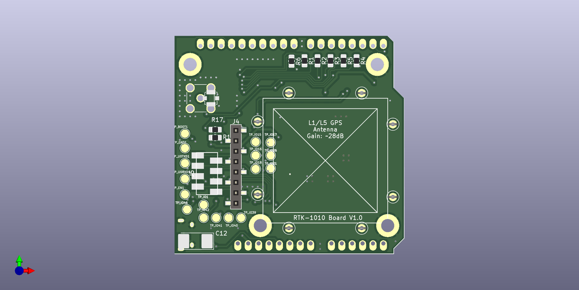
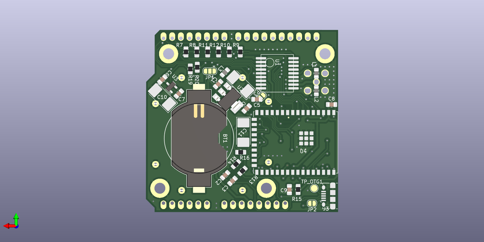
| Qty | Value | Footprint | References |
|---|---|---|---|
| 18 | TestPoint | TestPoint:TestPoint_Pad_D2.0mm | TP_BOOT1, TP_EN1, TP_GND1, TP_IO1, TP_IO15, TP_IO16, TP_IO17, TP_IO18, TP_IO21, TP_IO26, TP_IO39, TP_IO40, TP_IO41, TP_IO42, TP_IO46, TP_OTG1 +2 |
| 17 | 100 | Resistor_SMD:R_0805_2012Metric_Pad1.20x1.40mm_HandSolder | R1, R2, R3, R4, R5, R6, R7, R8, R10, R11, R12, R13, R14, R15, R19, R20 +1 |
| 8 | TestPoint | TestPoint:TestPoint_Loop_D2.50mm_Drill1.0mm | TP1, TP2, TP3, TP4, TP5, TP6, TP7, TP8 |
| 7 | 100nF | Capacitor_SMD:C_0805_2012Metric_Pad1.18x1.45mm_HandSolder | C1, C4, C5, C6, C7, C8, C9 |
| 4 | 10uF | Capacitor_Tantalum_SMD:CP_EIA-7132-20_AVX-U_Pad2.72x3.50mm_HandSolder | C10, C11, C12, C13 |
| 4 | MountingHole_Pad | MountingHole:MountingHole_3.2mm_M3_DIN965_Pad | H1, H2, H3, H4 |
| 3 | 10k | Resistor_SMD:R_0805_2012Metric_Pad1.20x1.40mm_HandSolder | R16, R17, R18 |
| 2 | 100pF | Capacitor_SMD:C_0805_2012Metric_Pad1.18x1.45mm_HandSolder | C2, C3 |
| 2 | 39nH | Inductor_SMD:L_0805_2012Metric_Pad1.15x1.40mm_HandSolder | L1, L2 |
| 1 | 1.2uH | Inductor_SMD:L_0805_2012Metric_Pad1.15x1.40mm_HandSolder | L3 |
| 1 | 3.3V | Battery:BatteryHolder_Keystone_1058_1x2032 | BT1 |
| 1 | Arduino_Uno_Shield | MyModules:Arduino_Uno_Shield | XA1 |
| 1 | BNO055 | Connector_PinSocket_2.54mm:PinSocket_1x08_P2.54mm_Vertical_SMD_Pin1Right | J4 |
| 1 | Conn_GPS | footprints:CONN-TE-MICROMATCH-4X2-SMD | J5 |
| 1 | ESP32-S2-WROVER | Espressif:ESP32-S2-WROVER | U4 |
| 1 | IPEX | Connector_Coaxial:U.FL_Molex_MCRF_73412-0110_Vertical | J2 |
| 1 | MCP1700-3302E_SOT23 | Package_TO_SOT_SMD:SOT-23 | U3 |
| 1 | NCP1117-3.3_SOT223 | Package_TO_SOT_SMD:SOT-223-3_TabPin2 | U2 |
| 1 | RTK-1010 | locosystech:rtk1010 | U1 |
| 1 | SMA | Connector_Coaxial:SMA_Amphenol_132134-11_Vertical | J1 |
| 1 | SolderJumper_3_Open | Jumper:SolderJumper-3_P1.3mm_Open_RoundedPad1.0x1.5mm | JP1 |
| 1 | USB power | Jumper:SolderJumper-2_P1.3mm_Open_RoundedPad1.0x1.5mm | JP2 |
| 1 | USB_OTG | Connector_USB:USB_Micro-B_Amphenol_10118194_Horizontal | J3 |
| 1 | VCC_IO | Jumper:SolderJumper-2_P1.3mm_Open_RoundedPad1.0x1.5mm | JP3 |
It measures 56.2 × 53.3 mm and has 2 copper layers, 1.6 mm thick.
80 parts, built around the ESP32-S2-WROVER-I(4M) and BNO055. The full list of its parts is on this page, with links to each part's symbol and footprint where PCBKit's library has them.
From the MS71/RTK1010Board repository on GitHub, at the commit this page was made from: the board is kicad/RTK1010Board.kicad_pcb and its schematic kicad/RTK1010Board.kicad_sch. PCBKit opens the board in the browser, with nothing to install.
Its repository states no licence, so its author keeps all rights: ask MS71 before reusing the design.
GaudiLabs/qPocketPCR
Quantitative PCR machine detecting fluorescence using a camera

gcormier/alarmbuddy
The output current for sensors is limited to a few milliamps.

DevKiDCosmo/SATELLITE-EDGE-MODULE
A satellite edge module ready for competition


HexaBitsEdu/ESP32-MiniDrone
this project is a drone based on esp32 microcontroller and coreless DC motor

jildertviet/ESP32S2_MIDI_controller
ESP32S2 based MIDI controller with 5 sliders


madpilot/kegerator
Replacement ESP32-based control board for the Keg King kegerator