4 layers98 × 48 mm
Esphome pressure
gcormier/esphome-pressure
esphome board with a differential pressure sensor, supporting a variety of power sources
51 parts102

 gcormier/alarmbuddy22
The output current for sensors is limited to a few milliamps.
Alarmbuddy is an open-source printed circuit board by gcormier, from the gcormier/alarmbuddy repository on GitHub. It is a 2-layer board of 81 × 59 mm with 34 parts on 50 nets, routed with 245 tracks and 40 vias.
It is built around the ESP32-S2-WROVER-I(4M), BD9G101G-TR and SS210. Its parts include 7 capacitors, 7 connectors, 6 resistors, 5 diodes and 2 ICs. It belongs with the ESP32 boards of this library.


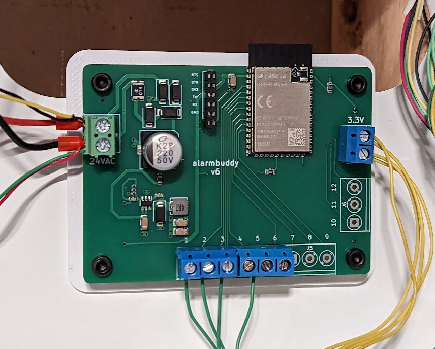
This is an ESP32-S2 board which can read up to 12 inputs. It can be programmed with custom software, or flashed with esphome to integrate easily with Home Assistant. The main goal is to replace an old alarm panel with one that can use all of the existing passive sensors but use Home Assistant for the automation and alerting.
If you are interested in a fully built version I sell them on my tindie store, Greg's Tinker Town
It is meant to be powered by 10-24VAC, a common supply voltage for alarm systems in North America. The current draw should be only 10-30mA. The minimum DC voltage is 7V - using a 5V USB power supply will not work. A 12VDC power supply would be required.
The unit will work with any input that works in a similar manner to a contact switch or relay - completing and breaking the circuit to indicate a status change. Sensors that send voltage are not supported. Standard door and window sensors work in this manner. If there are other active sensors that need power (eg. break glass sensor, motion sensor), and operate in this manner, then they should work as well. (You will need to get power to these sensors independently of the board)
The output current for sensors is limited to a few milliamps.
11 of the inputs on the ESP-S2 that are used support analog reads.For those with analog sensors or resistors used to detect cut wires, you could likely handle these scenarios. I have not done any testing in this regards as all my sensors are simple on/off.
The holes are sized for M3 bolts. There is no hardware on the back of the board, so as long as adequate electrical insulation is provided, double-sided foam tape could be used. An STL for a mounting plate is provided as well if you have access to a 3D printer.
If you are using a purchased unit, it has been pre-flashed with esphome with the captive portal enabled. This will allow you to connect via WiFi directly to the device to configure your WiFi. Unless you brick your device with bad settings, you should never need to physically flash your device with a serial adapter.
Power on the device and wait 30-60 seconds for it to setup the captive portal.
Look for "AlarmBuddy Fallback" on your phone/computer and connect to it.

Enter "alarmbuddy" as the password.

Once connected, you should be prompted to Sign In - click on this option.

You can then choose your WiFi SSID and enter the password. The device will connect to this, and the setting will remain unless you flash or upload a new esphome configuration. If the device fails to connect to this network at any point, it will revery to the captive portal on the AlarmbuddyFallback SSID.

The RTS and DTR programming pins are swapped for GPIO0 and EN. If you are programming your device via WiFi with esphome, you will not run into any issuse. Should you ever brick your device and need to flash it from a serial adapter, you will need to ensure you swap these 2 wires when connecting your programmer.
| Qty | Value | Footprint | References |
|---|---|---|---|
| 5 | SS210 | Diode_SMD:D_SMA | D1, D2, D3, D4, D5 |
| 2 | 100 | Resistor_SMD:R_0402_1005Metric | R4, R11 |
| 2 | 10K | Resistor_SMD:R_0805_2012Metric | R5, R6 |
| 2 | 10u | Capacitor_SMD:C_1206_3216Metric | C1, C7 |
| 2 | 47u | Capacitor_SMD:C_1206_3216Metric | C2, C3 |
| 1 | 0.1u 25v | Capacitor_SMD:C_0603_1608Metric | C4 |
| 1 | 140mA hold / 340mA trip mSMD014 | Fuse:Fuse_1812_4532Metric | F1 |
| 1 | 15nF | Capacitor_SMD:C_0603_1608Metric | C5 |
| 1 | 1k5 | Resistor_SMD:R_0402_1005Metric | R12 |
| 1 | 24VAC | TerminalBlock_Phoenix:TerminalBlock_Phoenix_MKDS-1,5-2-5.08_1x02_P5.08mm_Horizontal | J1 |
| 1 | 3V3 | TerminalBlock_Phoenix:TerminalBlock_Phoenix_PT-1,5-2-5.0-H_1x02_P5.00mm_Horizontal | J2 |
| 1 | 4.7u | Inductor_SMD:L_Sunlord_MWSA0402S | L1 |
| 1 | 470 | Resistor_SMD:R_0402_1005Metric | R2 |
| 1 | 470uF 50V | Capacitor_SMD:CP_Elec_10x10 | C6 |
| 1 | 600@100MHz | Inductor_SMD:L_0805_2012Metric | FB1 |
| 1 | BD9G101G | Package_TO_SOT_SMD:SOT-23-6 | U1 |
| 1 | ESP32-S2-WROVER | RF_Module:ESP32-S2-WROVER | U2 |
| 1 | SENS1-3 | TerminalBlock_Phoenix:TerminalBlock_Phoenix_PT-1,5-3-5.0-H_1x03_P5.00mm_Horizontal | J3 |
| 1 | SENS10-12 | TerminalBlock_Phoenix:TerminalBlock_Phoenix_PT-1,5-3-5.0-H_1x03_P5.00mm_Horizontal | J6 |
| 1 | SENS4-6 | TerminalBlock_Phoenix:TerminalBlock_Phoenix_PT-1,5-3-5.0-H_1x03_P5.00mm_Horizontal | J4 |
| 1 | SENS7-9 | TerminalBlock_Phoenix:TerminalBlock_Phoenix_PT-1,5-3-5.0-H_1x03_P5.00mm_Horizontal | J5 |
| 1 | eflashy32 | Connector_PinHeader_2.54mm:PinHeader_1x06_P2.54mm_Vertical | J7 |
The 30 most common of 34 parts.
gcormier/esphome-pressure
esphome board with a differential pressure sensor, supporting a variety of power sources

gcormier/espairqual
esphome board to interface with a few air quality (PM) sensors


GaudiLabs/qPocketPCR
Quantitative PCR machine detecting fluorescence using a camera


DevKiDCosmo/SATELLITE-EDGE-MODULE
A satellite edge module ready for competition
It measures 81 × 59 mm and has 2 copper layers, 1.6 mm thick.
34 parts, built around the ESP32-S2-WROVER-I(4M), BD9G101G-TR and SS210. The full list of its parts is on this page, with links to each part's symbol and footprint where PCBKit's library has them.
From the gcormier/alarmbuddy repository on GitHub, at the commit this page was made from: the board is pcb/alarmbuddy.kicad_pcb and its schematic pcb/alarmbuddy.kicad_sch. PCBKit opens the board in the browser, with nothing to install.
Its repository states no licence, so its author keeps all rights: ask gcormier before reusing the design.