2 layers51 × 20 mm
Hybrid
gcormier/esphome-pressure
esphome board with a differential pressure sensor, supporting a variety of power sources
7 parts102

 gcormier/esphome-pressure102
esphome board with a differential pressure sensor, supporting a variety of power sources
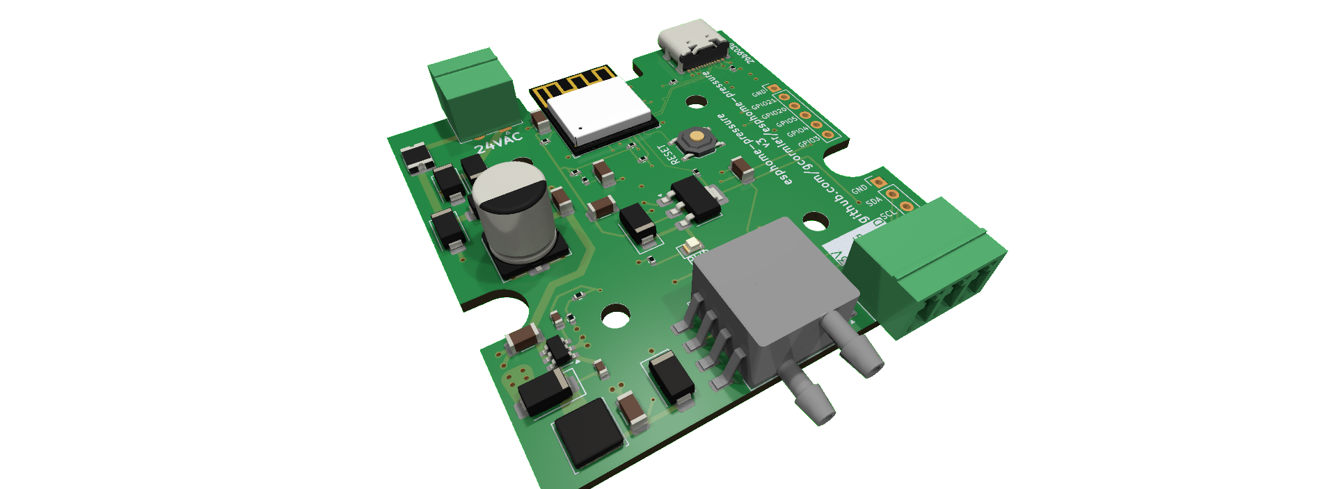
Esphome pressure is an open-source printed circuit board by gcormier, from the gcormier/esphome-pressure repository on GitHub. It is a 4-layer board of 98 × 48 mm with 51 parts on 54 nets, routed with 393 tracks and 114 vias.
It is built around the ESP32-C3-MINI-1, BD9G101G-TR and AMS1117-3.3, with the SS210 and SMTSOM225BTR among its other parts. Its parts include 13 resistors, 12 capacitors, 8 diodes, 4 connectors and 3 ICs. It belongs with the home automation and IoT and sensors and measurement boards and the ESP32 and RISC-V boards of this library.


Purchase via my online store.
This is a custom device for reading differential pressure. The most useful example I can think of is monitoring your pressure drop across your air filter. This is a great way to know when to change your filter.
It is based on an ESP32-C3-MINI, which has native USB-C for flashing.
The pressure sensor part number will control the differential range that can be expected, as well as the accuracy (+/- 2%). I've chosen +/- 0.5kPa, which is about 2" of pressure drop. Most HVAC systems are designed to have a pressure drop of 0.1" (0.025kPa).
Version 3 (Dec 2024) is now available. It adds an additional pluggable header that will support Dallas 1-wire temperature sensors. The temperature sensor is optional, and the device will work without it. If you are using a Dallas DS18B20 sensor, I strongly recommend using Digikey, Mouser or Adafruit to avoid obtaining counterfeit sensors. Since these sensors use a 1-wire bus, and each have a unique ID, you can have as many sensors as you want using the single connection.
You will need to find out your sensor ID's as per the esphome documentation.
Sensor specifications:
It has a 500mA polyfuse directly off the screw terminal inputs to protect your HVAC system. The USB-C port is unfused and should be protected by the upstream device.
The USB-C port can be used to program. The first time, the reset button must be held. After this, all subsequent programming does not require access to the button.
The PCB will fit inside a Hammond 1593KBK or a Bud Industries HP-3650-B case. Both are available from Mouser, Digikey and elsewhere. You can either cut (CNC), fab (PCB) or 3D-print the faceplates. You can superglue some magnets in the case to have it stick to your HVAC system.
sensor:
  - platform: xgzp68xx
    temperature:
        name: "Temperature"
    pressure:
        name: "Differential Pressure"
        filters:
- offset: 40Note the sensor accuracy is +/- 2%. It is quite sensitive to pressure changes, so you may with to use other esphome filters in order to smooth out the values.
The following are based on feedback from users. If you would like to contribute something you've found to work well, please let me know via pull request, GitHub issue, or email.
| Size/Material | Sample Amazon Keywords | Comments |
|---|---|---|
| 2.5mm ID, 4mm OD polyurethane | Pneumatic Tubing - Polyurethane Air Compressor Hose Pipe, Apply to Air Line Transfer (4mm OD 2.5mm ID) | Works well, a bit stiff |
| 1/16" ID, 1/8" OD silicone | 1/16" ID x 1/8" OD Pure Thin Silicone Tubing Food Grade Pure Silicon Tube High Temp Home Brewing Winemaking Silicone Hose Tubing, 26.25ft Length | Very tight fit, suggest other sizes |
| 2mm ID, 4mm OD silicone | Pure Silicone Tubing, 2mm ID x 4mm OD High Temp Food Grade Tube Pure Silicone Hose Tube | Works well |
| 3mm ID, 5mm OD silicone | Too loose! Do not use |
There are now GPIO's broken out on a 2.54mm (0.1") header. The i2c bus is also broken out. These are all 3.3V logic pins, be careful not to source too much current from the power pins.
If you want to change the sensor to an absolute pressure sensor, the XGZP6887D appears to be footprint compatible. The code should also work, but you will need to set your K value according to the datasheet.
Please see https://github.com/gcormier/esphome-pressure/discussions/12 for more discussion and leave a comment if you are using it successfully.
The sensor is moving onto plug-in modules that use an SFP connector, so one main board can take different sensors. The interface (pinout, I²C/SPI/UART, +3V3/+5V, module lengths) is specified in interface/INTERFACE.md.
pcb/                  main board (the carrier)
interface/            shared SensorModule symbol, SFP footprints, INTERFACE.md
modules/hybrid/       sensor module: fits an SDP810 or an XGZP6899D on one board
modules/skeleton/     blank L42 module to start new ones from (hole grid, keepouts)
Every project references interface/ relatively, so nothing needs configuring in KiCad.
The main board is released with pcb-v<N> tags; a module with <project>-v<N>, eg hybrid-v1.
| Qty | Value | Footprint | References |
|---|---|---|---|
| 10 | 5k1 | Resistor_SMD:R_0402_1005Metric | R1, R3, R4, R5, R7, R8, R9, R10, R11, R13 |
| 7 | 10uF 50V | Capacitor_SMD:C_1206_3216Metric | C1, C6, C7, C8, C9, C11, C12 |
| 7 | SS210 | Diode_SMD:D_SMA | D1, D2, D3, D4, D5, D6, D7 |
| 4 | MountingHole | MountingHole:MountingHole_3.2mm_M3 | H101, H102, H103, H104 |
| 3 | 0.1u 25v | Capacitor_SMD:C_0603_1608Metric | C2, C3, C4 |
| 2 | 680 | Resistor_SMD:R_0402_1005Metric | R2, R6 |
| 1 | 100uF 50V | Capacitor_SMD:CP_Elec_8x10 | C10 |
| 1 | 140mA hold / 340mA trip mSMD014 | Fuse:Fuse_1812_4532Metric | F1 |
| 1 | 15nF | Capacitor_SMD:C_0603_1608Metric | C5 |
| 1 | 24VAC | Connector_Phoenix_MC:PhoenixContact_MC_1,5_2-G-3.81_1x02_P3.81mm_Horizontal | J1 |
| 1 | 3k9 | Resistor_SMD:R_0402_1005Metric | R12 |
| 1 | 6.8uH | Inductor_SMD:L_Sunlord_SWPA5012S | L1 |
| 1 | AMS1117-3.3 | Package_TO_SOT_SMD:SOT-223-3_TabPin2 | U3 |
| 1 | BD9G101G | Package_TO_SOT_SMD:SOT-23-6 | U1 |
| 1 | ESP32-C3-MINI-1 | Espressif:ESP32-C3-MINI-1 | U4 |
| 1 | M2 nut 10 mm | Mounting_Wuerth:Mounting_Wuerth_WA-SMSI-M2_H2.5mm_9774025243 | H9 |
| 1 | M2 nut 2.925 mm | Mounting_Wuerth:Mounting_Wuerth_WA-SMSI-M2_H2.5mm_9774025243 | H5 |
| 1 | M2 nut 34 mm | Mounting_Wuerth:Mounting_Wuerth_WA-SMSI-M2_H2.5mm_9774025243 | H7 |
| 1 | M2 nut 40 mm | Mounting_Wuerth:Mounting_Wuerth_WA-SMSI-M2_H2.5mm_9774025243 | H8 |
| 1 | PWR | LED_SMD:LED_0805_2012Metric | D8 |
| 1 | RESET | Button_Switch_SMD:SW_Push_1P1T_XKB_TS-1187A | SW1 |
| 1 | SensorModule | sensor_module:SFP+ | J6 |
| 1 | T1 | Connector_Phoenix_MC:PhoenixContact_MC_1,5_3-G-3.81_1x03_P3.81mm_Horizontal | J5 |
| 1 | USBC | Connector_USB:USB_C_Receptacle_GCT_USB4105-xx-A_16P_TopMnt_Horizontal | J4 |

gcormier/espairqual
esphome board to interface with a few air quality (PM) sensors

gcormier/alarmbuddy
The output current for sensors is limited to a few milliamps.


Diode663/USBC_M2E_HaLow_Adapter
USB-C (USB 2.0) to M.2 Key-E carrier for the Gateworks GW16170 Wi-Fi HaLow card. KiCad 10, generated from Python, Rev A sent to JLCPCB.


nordstream3/FOC
Date | Manufacturer | amount | includes | shipping & tax | price | -------- | -------- | -------- | -------- | -------- | -------- | 2024-01-17 | JLCPCB | 10 boards | All assembled excl fets and caps | YES, to EU |…
It measures 98 × 48 mm and has 4 copper layers, 1.6 mm thick.
51 parts, built around the ESP32-C3-MINI-1, BD9G101G-TR, AMS1117-3.3 and SS210. The full list of its parts is on this page, with links to each part's symbol and footprint where PCBKit's library has them.
From the gcormier/esphome-pressure repository on GitHub, at the commit this page was made from: the board is pcb/esphome-pressure.kicad_pcb and its schematic modules/hybrid/hybrid.kicad_sch. PCBKit opens the board in the browser, with nothing to install.
Its repository states no licence, so its author keeps all rights: ask gcormier before reusing the design.
