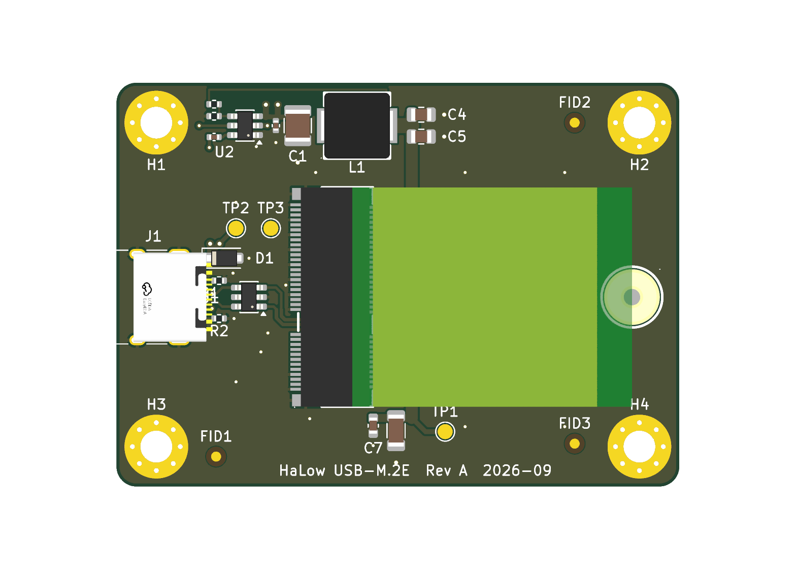
USBC M2E HaLow Adapter is an open-source printed circuit board by Diode663, from the Diode663/USBC_M2E_HaLow_Adapter repository on GitHub, published under the CERN-OHL-P-2.0 licence. It is a 2-layer board of 56.5 × 40.5 mm with 30 parts on 63 nets, routed with 125 tracks and 44 vias.
It is built around the TPS563201DDCR, USBLC6-2SC6 and CL21A226MAQNNNE, with the CL31A107MQHNNNE, CYA0630-2.2UH and FRC0402F3322TS among its other parts. Its parts include 9 capacitors, 4 resistors, 2 ICs, 2 connectors and 1 diode. It belongs with the radio and wireless and computers and single-board computers boards of this library.
USB 2.0 over a USB-C receptacle to an M.2 2230 Key-E socket, for the Gateworks
GW16170 (Morse Micro MM8108-M20) Wi-Fi HaLow card. 56.5 x 40.5 mm, 2-layer
(JLCPCB JLC0216A), single-sided assembly.
Status: Rev A is built and works as designed (boards assembled by JLCPCB, confirmed by the
author on 2026-09-29). The project is closed; no Rev B is planned.
Test procedure: docs/Test_Procedure.md. Pre-fabrication review:
docs/Design_Review_2026-09-20.md.
H1-H4 M3, H5 SMTSOM225BTR M2 x 2.5 mm SMT nut for the card
Only USB D+/D- (M.2 pins 3 and 5), 3.3 V and ground go to the card. W_DISABLE1# (the card's
reset) and W_DISABLE2# (wake) are left open on purpose: the card has its own pull-ups, and its
reset pin uses a power-on RC that an external pull-up would defeat.
--place resets every unlocked footprint. Designators moved by hand in KiCad are detected and
kept (.pcbgen-refs.json). route_board.py redraws every track, via and pour each time it runs.
build_package.py writes fab/ and refuses to run unless DRC is clean.
Mechanical facts, from the MLD-NGFF-E-4.2H drawing:
the card extends from the even-pin / locating-peg side of the socket;
the card stop is 1.75 mm behind the pegs, so the 2230 notch is 29.75 mm from the socket centre;
the card's underside is 2.52 mm above the board; parts under it must be 0.90 mm or lower.
JLCPCB: setup_fab.py writes their 2-layer rules into the project and into
USBC_M2E_HaLow_Adapter.kicad_dru, with the source pages and date in its docstring. The USB pair
is 0.3345 / 0.1524 mm with ground pour 0.2032 mm either side, from JLCPCB's own calculator for
stackup JLC0216A. JLCPCB does not test impedance on 2-layer boards. jlc_rotations.json holds
the placement-file corrections with the evidence for each.
Repository contents
USBC_M2E_HaLow_Adapter.kicad_*: the KiCad 10 project, schematic, routed board and custom design rules.
fab/: the package sent to JLCPCB for Rev A (gerbers zip, BOM, placement file, order notes).
docs/: schematic PDF, renders, copper images, the pre-fabrication design review and the board test procedure.
library/: project symbols, footprints and 3D models.
*.py: the generators. schlib.py, subcircuits.py, pcblib.py, autoplace.py, recipes.py and jlc_cpl.py are copies of the libraries the project was generated with.
Vendor datasheets are not included.
Licence
Copyright Diode663 2026.
Hardware (the KiCad project, schematic, board, the project's own symbols and footprints,
fabrication outputs and documentation): this source describes Open Hardware and is licensed under
the CERN-OHL-P v2. You may redistribute and modify this source and make products using it under
the terms of the CERN-OHL-P v2 (https://ohwr.org/cern_ohl_p_v2.txt), a copy of which is in
LICENSE. This source is distributed WITHOUT ANY EXPRESS OR IMPLIED WARRANTY,
INCLUDING OF MERCHANTABILITY, SATISFACTORY QUALITY AND FITNESS FOR A PARTICULAR PURPOSE. Please
see the CERN-OHL-P v2 for applicable conditions.
Source location: https://github.com/Diode663/USBC_M2E_HaLow_Adapter
Not covered by either licence — third-party material, included for convenience and owned by
its respective rights holders:
footprints and 3D models obtained from LCSC / EasyEDA with easyeda2kicad:
library/HaLowAdapter.pretty/CONN-SMD_MLD-NGFF-E-4.2H.kicad_mod, IND-SMD_L7.2-W6.6_GPSR07X0.kicad_mod,
SMTSO_M2_H2.5_SMTSOM225BTR.kicad_mod, and in library/HaLowAdapter.3dshapes/ the
USB-C_SMD-TYPE-C-31-M-12_1, IND-SMD_L7.2-W6.6-H3.0_GPSR07X0 and SMD_BD5.6-D3.6 models;
USB_C_Receptacle_HRO_TYPE-C-31-M-12.kicad_mod and the M.2 socket symbol, which are modified
copies from the KiCad libraries (CC-BY-SA 4.0 with the KiCad library exception).
Gateworks, Morse Micro, JLCPCB and the part manufacturers are not affiliated with this project.
Theoros is a USB-C GPS logger and LoRa tracker built on the ESP32-S3. It logs 1 Hz u-blox M10 fixes to microSD, shows status on an OLED and sends AES-128-CCM encrypted position over 868 MHz LoRa.
Six open power and charging boards: KiCad 10, JLCPCB-ready, CERN-OHL-S-2.0
34 partsCERN-OHL-S-2.0
Questions
How big is the USBC M2E HaLow Adapter PCB?
It measures 56.5 × 40.5 mm and has 2 copper layers, 1.6 mm thick.
What parts does the USBC M2E HaLow Adapter use?
30 parts, built around the TPS563201DDCR, USBLC6-2SC6, CL21A226MAQNNNE and CL31A107MQHNNNE. The full list of its parts is on this page, with links to each part's symbol and footprint where PCBKit's library has them.
Where can I download the USBC M2E HaLow Adapter KiCad files?
From the Diode663/USBC_M2E_HaLow_Adapter repository on GitHub, at the commit this page was made from: the board is USBC_M2E_HaLow_Adapter.kicad_pcb and its schematic USBC_M2E_HaLow_Adapter.kicad_sch. PCBKit opens the board in the browser, with nothing to install.
Can I use the USBC M2E HaLow Adapter design in my own project?
Its repository publishes it under the CERN-OHL-P-2.0 licence: you may reuse it on that licence's terms (keep the author's notice, and for a copyleft licence share your changes alike).