7-segment LED
mrmtmtk03/7-segment_LED
なお、点灯させるためには、この他にArduino UNOが必要である。 ## プリント基板の作成 設計した基板データは本リポジトリで公開している。 例えば、JLCPCBであればこのZIPファイル 7-segmentLED02kicad\production\7-segmentLED02kicad.zipをgerber fileとしてアップロードすることで基板の発注ができる。

なお、点灯させるためには、この他にArduino UNOが必要である。 ## プリント基板の作成 設計した基板データは本リポジトリで公開している。 例えば、JLCPCBであればこのZIPファイル 7-segmentLED02kicad\production\7-segmentLED02kicad.zipをgerber fileとしてアップロードすることで基板の発注ができる。
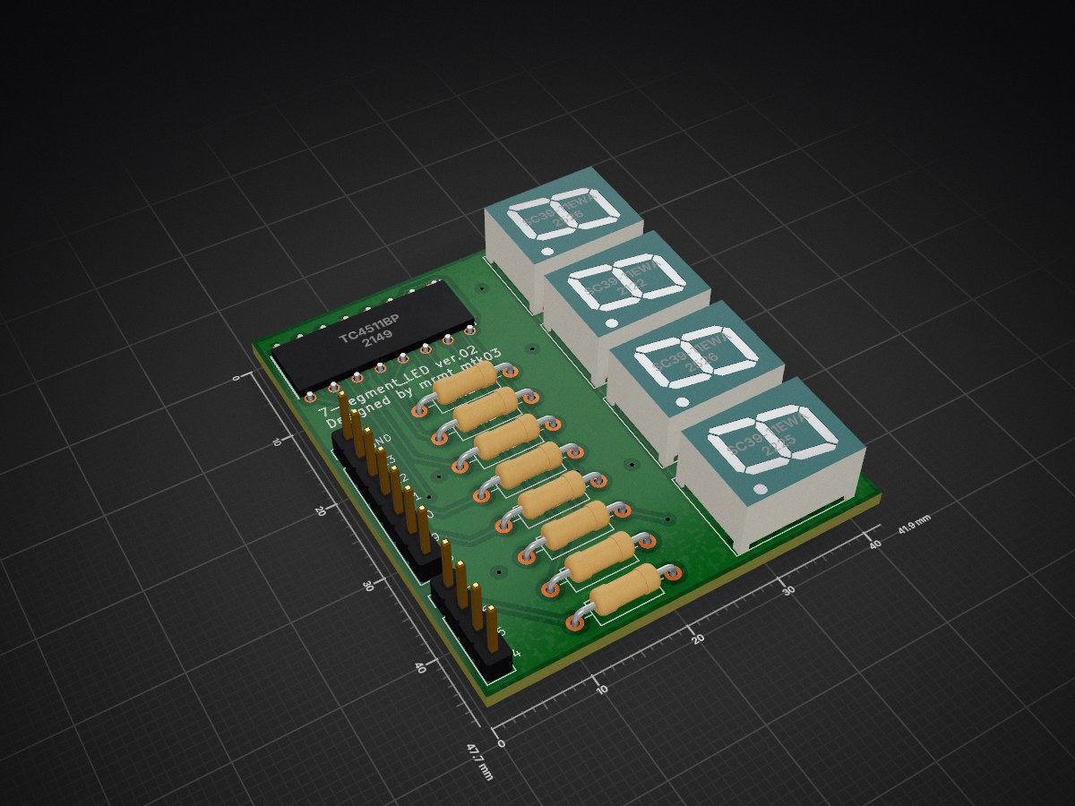
7-segment LED 02 kicad is an open-source printed circuit board by mrmtmtk03, from the mrmtmtk03/7-segment_LED repository on GitHub. It is a 2-layer board of 41.9 × 47.7 mm with 15 parts on 26 nets, routed with 195 tracks and 21 vias.
It is built around the SC39-11EWA. Its parts include 8 resistors, 5 ICs and 1 connector.
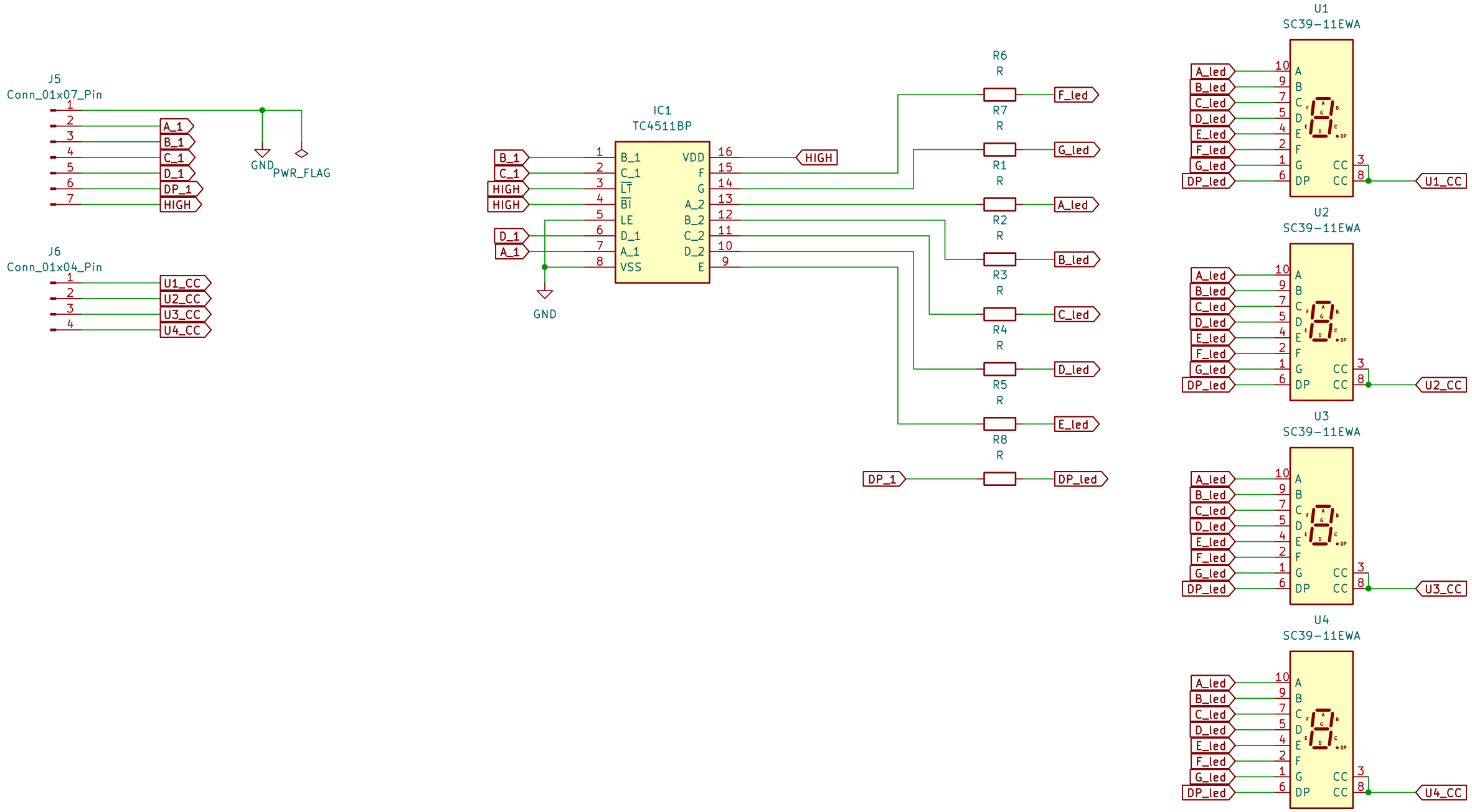
KiCadにて回路図を作成した。
7セグメントデコーダー(TC4511BP)を使用して、4つの7セグメントLEDをArduino UNOによりダイナミック点灯する回路である。

使用する7セグメントLEDはカソードコモンで、データシートより順方向電圧$V_F=3.5\,[\mathrm{V}]$、順方向電流の絶対最大定格は$I_F=35\,[\mathrm{mA}]$である。
今回は$I_F=4.5\,[\mathrm{mA}]$となるように抵抗1を選定し以下のようにRを330 Ωと定める。
R_1=\frac{V-V_F}{I_F}=\frac{5-3.5}{0.0045}≒330\,[\mathrm{Ω}]具体的な使用部品は以下の表に示す。
| 部品 | 型番 | 秋月電子販売コード |
|---|---|---|
| 7セグメントドライバー | TC4511BP | 114057 |
| 7セグメントLED | OSL10391-LRA | 130319 |
| 抵抗器 | 330 Ω | 107812 |
| 丸ピンICソケット(16P) | 2227MC-16-03 | 100029 |
| 細ピンヘッダー(オスL型) 1×12 | PHA-1x12RG | 111573 |
なお、点灯させるためには、この他にArduino UNOが必要である。
設計した基板データは本リポジトリで公開している。
例えば、JLCPCBであればこのZIPファイル 7-segment_LED_02_kicad\production\7-segment_LED_02_kicad.zipをgerber fileとしてアップロードすることで基板の発注ができる。
ただし、基板の発注内容に誤りがあった場合、その結果生じた発注者の不利益について、当方は責任を負いかねますので、十分ご注意ください。
| Qty | Value | Footprint | References |
|---|---|---|---|
| 8 | R | Resistor_THT:R_Axial_DIN0207_L6.3mm_D2.5mm_P10.16mm_Horizontal | R1, R2, R3, R4, R5, R6, R7, R8 |
| 4 | SC39-11EWA | Display_7Segment:Sx39-1xxxxx | U1, U2, U3, U4 |
| 1 | Conn_01x04_Pin | Connector_PinHeader_2.54mm:PinHeader_1x04_P2.54mm_Vertical | J6 |
| 1 | Conn_01x07_Pin | Connector_PinHeader_2.54mm:PinHeader_1x07_P2.54mm_Vertical | GND |
| 1 | TC4511BP | TC4511BP:DIP762W60P254L1975H445Q16N | IC1 |

mrmtmtk03/7-segment_LED
なお、点灯させるためには、この他にArduino UNOが必要である。 ## プリント基板の作成 設計した基板データは本リポジトリで公開している。 例えば、JLCPCBであればこのZIPファイル 7-segmentLED02kicad\production\7-segmentLED02kicad.zipをgerber fileとしてアップロードすることで基板の発注ができる。

hemilth2257/Temperature-Controlled-DC-Fan
Temperature Controlled DC fan built with an Arduino Nano, LM358 op-amp, and a custom KiCad PCB


google/mozc-devices
Circuit diagrams and firmware source code for Gboard DIY keyboards

hoglet67/RGBtoHDMI
Bare-metal Raspberry Pi project that provides pixel-perfect sampling of Retro Computer RGB/YUV video and conversion to HDMI

mntmn/amiga2000-gfxcard
MNT VA2000, an Open Source Amiga 2/3/4000 Graphics Card (Zorro II/III), written in Verilog

hackclub/OnBoard
💡 Join 1,000 teenagers and make your first PCB with a $100 grant!

kenp-io/not-for-airpods-repairs
The content of this repository is licensed under the WTFPL License. Please have a close look at the terms before using this material.
It measures 41.9 × 47.7 mm and has 2 copper layers, 1.6 mm thick.
15 parts, built around the SC39-11EWA. The full list of its parts is on this page, with links to each part's symbol and footprint where PCBKit's library has them.
From the mrmtmtk03/7-segment_LED repository on GitHub, at the commit this page was made from: the board is 7-segment_LED_02_kicad/7-segment_LED_02_kicad.kicad_pcb and its schematic 7-segment_LED_02_kicad/7-segment_LED_02_kicad.kicad_sch. PCBKit opens the board in the browser, with nothing to install.
Its repository states no licence, so its author keeps all rights: ask mrmtmtk03 before reusing the design.