
7-segment LED 02 kicad
mrmtmtk03/7-segment_LED
なお、点灯させるためには、この他にArduino UNOが必要である。 ## プリント基板の作成 設計した基板データは本リポジトリで公開している。 例えば、JLCPCBであればこのZIPファイル 7-segmentLED02kicad\production\7-segmentLED02kicad.zipをgerber fileとしてアップロードすることで基板の発注ができる。

Temperature Controlled DC fan built with an Arduino Nano, LM358 op-amp, and a custom KiCad PCB
Tempcontrolfan is an open-source printed circuit board by hemilth2257, from the hemilth2257/Temperature-Controlled-DC-Fan repository on GitHub. It is a 2-layer board of 87.6 × 79.4 mm with 20 parts on 44 nets, routed with 146 tracks and 4 vias.
It is built around the LM358, SC39-11EWA and BD139. Its parts include 10 resistors, 3 ICs, 2 connectors, 1 diode and 1 transistor. It belongs with the audio and music boards and the AVR (ATmega, ATtiny) boards of this library.
Temperature Controlled DC fan built with an Arduino Nano, LM358 op-amp, and a custom KiCad PC
An automated cooling system built with an Arduino Nano, an LM358 op-amp, and an NTC thermistor. This project was developed during my 2nd semester of BTech in Electronics Engineering.
This hardware project bridges analog sensing and digital control. An NTC thermistor tracks the ambient temperature, and an LM358 op-amp acts as an open-loop comparator to trigger the cooling fan when the temperature exceeds a precise 40°C threshold. The Arduino Nano processes the ADC readings and multiplexes two 7-segment displays at 200 Hz for a flicker-free real-time temperature readout.
The system progressed from a dense breadboard prototype to a fully routed custom PCB designed in KiCad.
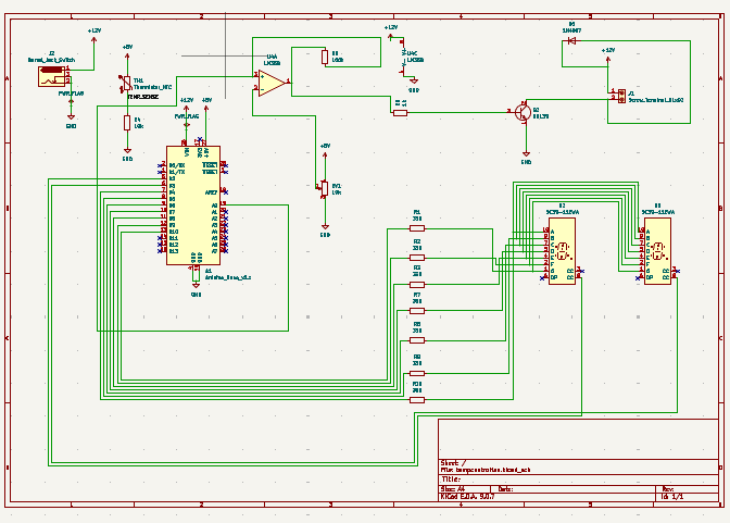
dc_fan_controller.ino: The main Arduino C++ source code.microproject_sem2_fixed.pdf: Full engineering project report, including circuit analysis, KiCad schematics, and testing methodologies.Here is the complete circuit schematic designed in KiCad:
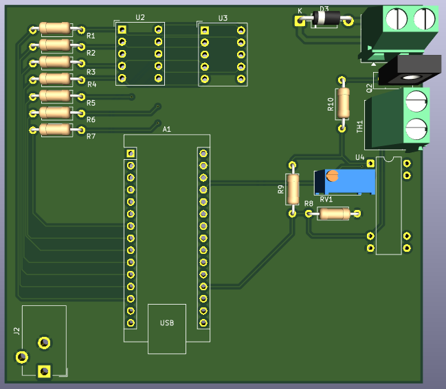
Here is the 3D render of the final routed board:
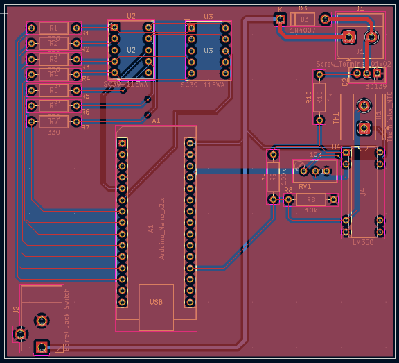
And here is the 2D copper track layout showing the strict 45-degree routing:
Hemil Thakkar & Het Dave Electronics Engineering Students at BVM Engineering College.
| Qty | Value | Footprint | References |
|---|---|---|---|
| 7 | 330 | Resistor_THT:R_Axial_DIN0207_L6.3mm_D2.5mm_P10.16mm_Horizontal | R1, R2, R3, R4, R5, R6, R7 |
| 2 | SC39-11EWA | Display_7Segment:Sx39-1xxxxx | U2, U3 |
| 1 | 100k | Resistor_THT:R_Axial_DIN0207_L6.3mm_D2.5mm_P10.16mm_Horizontal | R9 |
| 1 | 10k | Resistor_THT:R_Axial_DIN0207_L6.3mm_D2.5mm_P10.16mm_Horizontal | R8 |
| 1 | 10k | Potentiometer_THT:Potentiometer_Bourns_3296W_Vertical | RV1 |
| 1 | 1N4007 | Diode_THT:D_DO-41_SOD81_P10.16mm_Horizontal | D3 |
| 1 | 1k | Resistor_THT:R_Axial_DIN0207_L6.3mm_D2.5mm_P10.16mm_Horizontal | R10 |
| 1 | Arduino_Nano_v2.x | Module:Arduino_Nano | A1 |
| 1 | BD139 | Package_TO_SOT_THT:TO-126-3_Vertical | Q2 |
| 1 | Barrel_Jack_Switch | Connector_BarrelJack:BarrelJack_CUI_PJ-102AH_Horizontal | J2 |
| 1 | LM358 | Package_DIP:DIP-8-16_W7.62mm | U4 |
| 1 | Screw_Terminal_01x02 | TerminalBlock_Phoenix:TerminalBlock_Phoenix_MKDS-1,5-2-5.08_1x02_P5.08mm_Horizontal | J1 |
| 1 | Thermistor_NTC | TerminalBlock_Phoenix:TerminalBlock_Phoenix_MKDS-1,5-2-5.08_1x02_P5.08mm_Horizontal | TH1 |

mrmtmtk03/7-segment_LED
なお、点灯させるためには、この他にArduino UNOが必要である。 ## プリント基板の作成 設計した基板データは本リポジトリで公開している。 例えば、JLCPCBであればこのZIPファイル 7-segmentLED02kicad\production\7-segmentLED02kicad.zipをgerber fileとしてアップロードすることで基板の発注ができる。


Honyar55/Adjustable-Linear-DC-Power-Supply-PCB-Design-
A compact, 2-layer PCB implementation of an adjustable linear voltage regulator using an LM358 operational amplifier and a BD139 NPN pass transistor.This circuit takes a DC input voltage (e.g., $+15\text{V}$) and…


DylanLockyer/Black_Body
Electrical system for black body MKID tester

Matchboxscope/Matchboxscope
ESP32-based mini microscope for fluidic device observation
It measures 87.6 × 79.4 mm and has 2 copper layers, 1.6 mm thick.
20 parts, built around the LM358, SC39-11EWA and BD139. The full list of its parts is on this page, with links to each part's symbol and footprint where PCBKit's library has them.
From the hemilth2257/Temperature-Controlled-DC-Fan repository on GitHub, at the commit this page was made from: the board is Hardware_Design/tempcontrolfan.kicad_pcb and its schematic Hardware_Design/tempcontrolfan.kicad_sch. PCBKit opens the board in the browser, with nothing to install.
Its repository states no licence, so its author keeps all rights: ask hemilth2257 before reusing the design.