4 layers35.1 × 76.3 mm
Tiny4FSK
New-England-Weather-Balloon-Society/Tiny4FSK
Horus Binary v2 HAB Tracker
90 parts96CERN-OHL-W-2.0

 mpkendall/gumstik
a tiny uav flight computer
Tiny4FSK is an open-source printed circuit board by mpkendall, from the mpkendall/gumstik repository on GitHub, published under the CERN-OHL-W-2.0 licence. It is a 4-layer board of 18 × 63 mm with 86 parts on 90 nets, routed with 680 tracks and 142 vias.
It is built around the ATSAMD21G18A-AU, BME280 and TPS61200DRC, with the SI4463DY, TPS2116DRL and USBLC6-2SC6 among its other parts. Its parts include 32 capacitors, 16 resistors, 10 inductors, 9 ICs and 4 connectors. It belongs with the SAM D and SAM boards of this library.



WORK IN PROGRESS - Please do not rely on this as your only tracking system. Tiny4FSK is still in the R&D phase of development and testing.
NEW - Horus Binary v3! + quick lock mode and recovery mode
STATE - Main branch is stable!
Tiny4FSK aims to be an ultra-tiny high-altitude tracking system. It runs on 1 AA battery that lasts for 10-17 hours (packet interval and power output can be adjusted to lengthen battery life). It runs on 4FSK (4-frequency shift keying), which means that it separates tones into 4 separate frequencies. Upon this, it uses the Horus Binary v3 system, which is a relatively modern system popularly used with RS41ng.
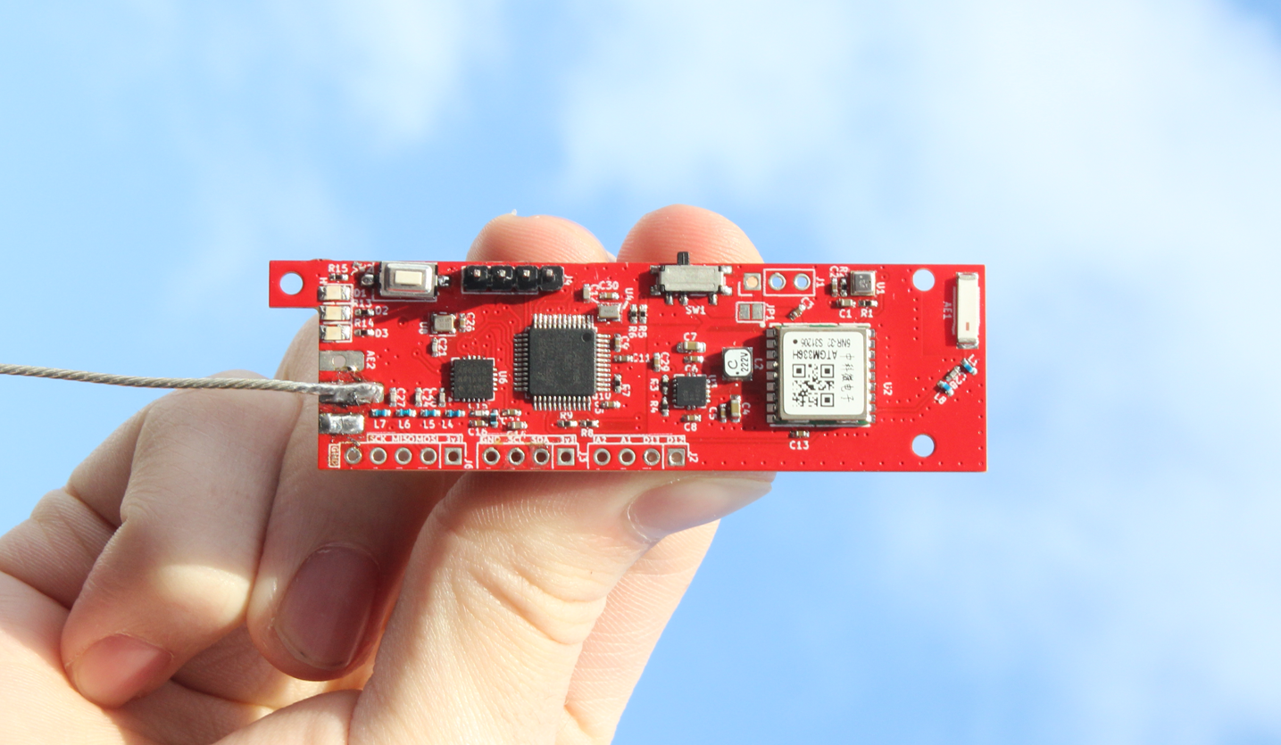
High altitude balloons (HABs) allow space science enthusiasts to launch their own payloads to near-space (30km) at a cost of hundreds of dollars instead of millions of dollars. This can be done for atmospheric research, breathtaking imagery, and scientific experimentation. While demanding meticulous planning, safety adherence, and technical skill in electronics and mechanics, this hobby rewards makers with a chance to get hands on with projects like electronic data loggers, camera systems, wireless communications, and more.
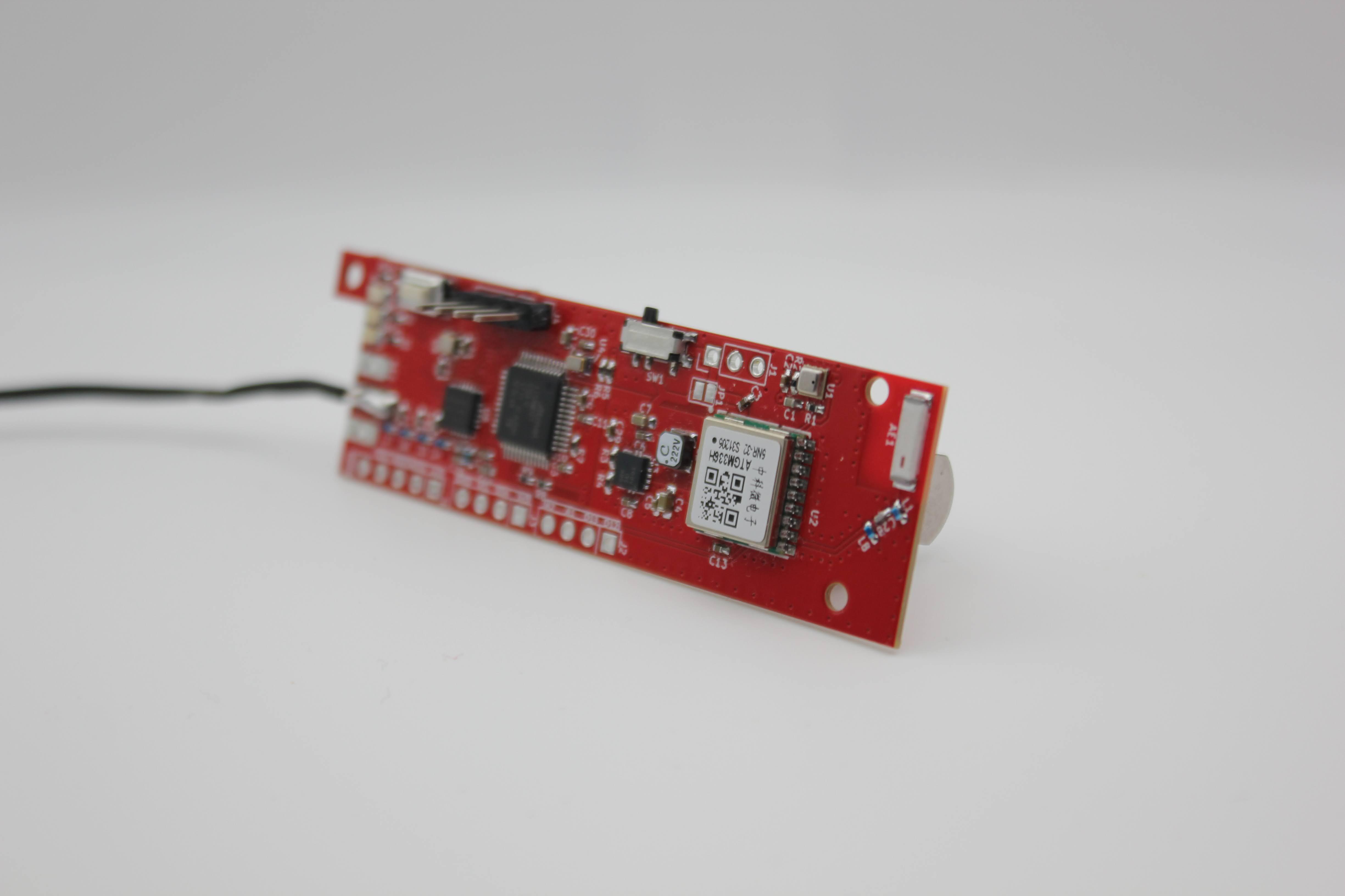
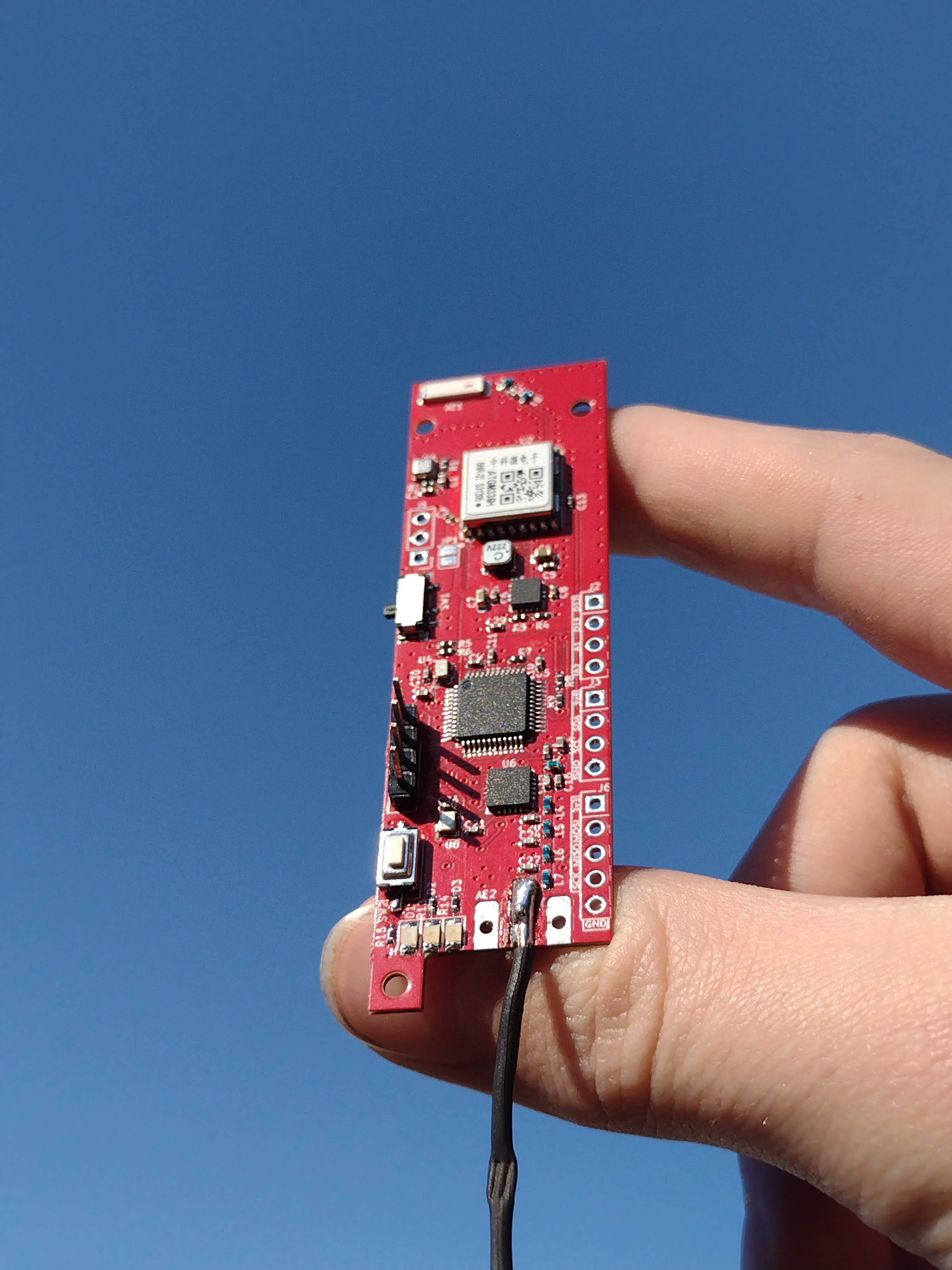
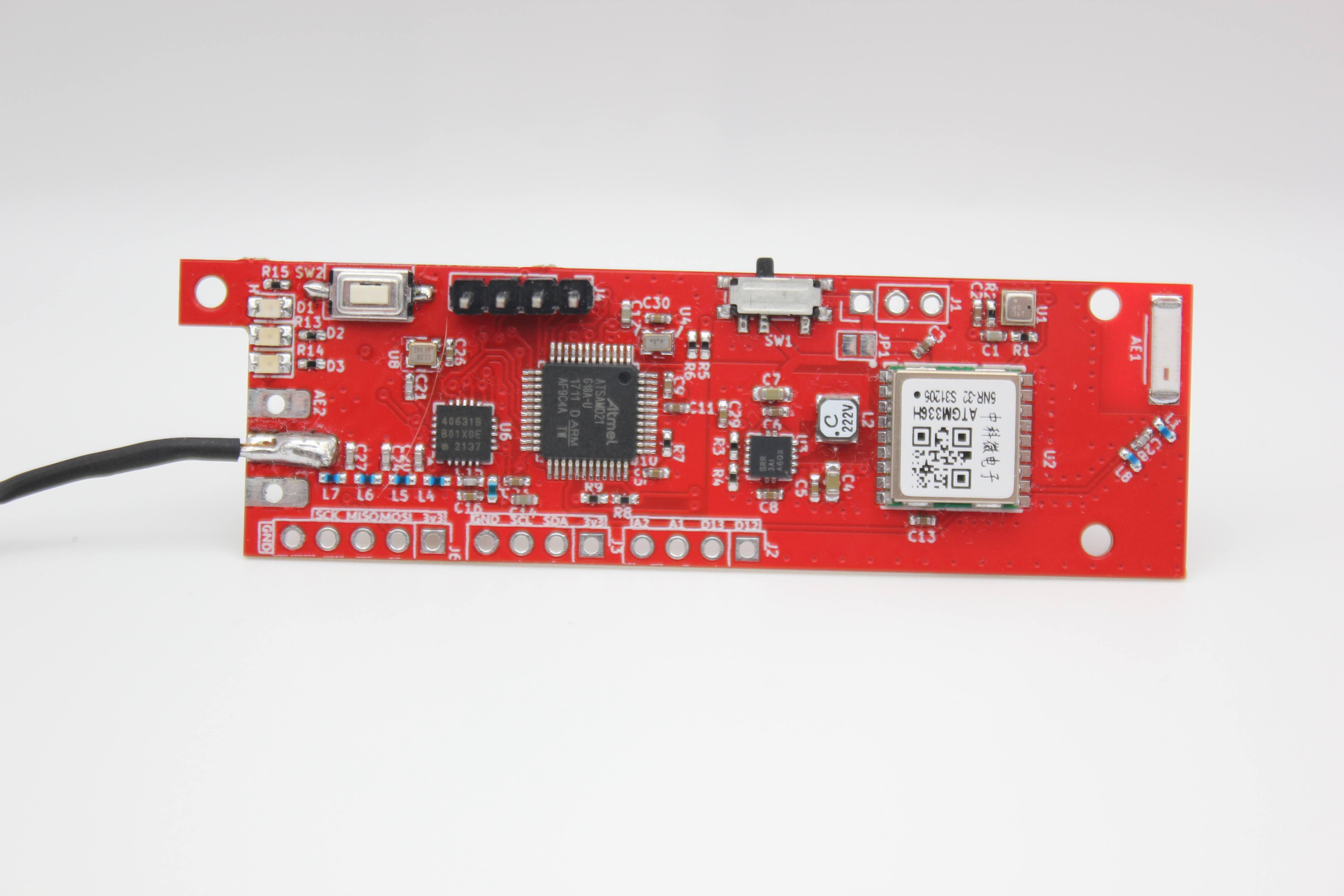
This codebase is meant to work with the Tiny4FSK PCB, also available on this GitHub repository. Key components include:
This list is not exhaustive. Additional components and passives are detailed in the schematic files.
This code is modular and separated into several different files for easy expansion. These files are listed below:
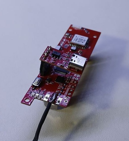
For pre-flight configuration, the USB board does not need to be broken off, and code can be uploaded normally by just plugging in the USB as it arrives. However, the breakout may be removed to save space during flights!
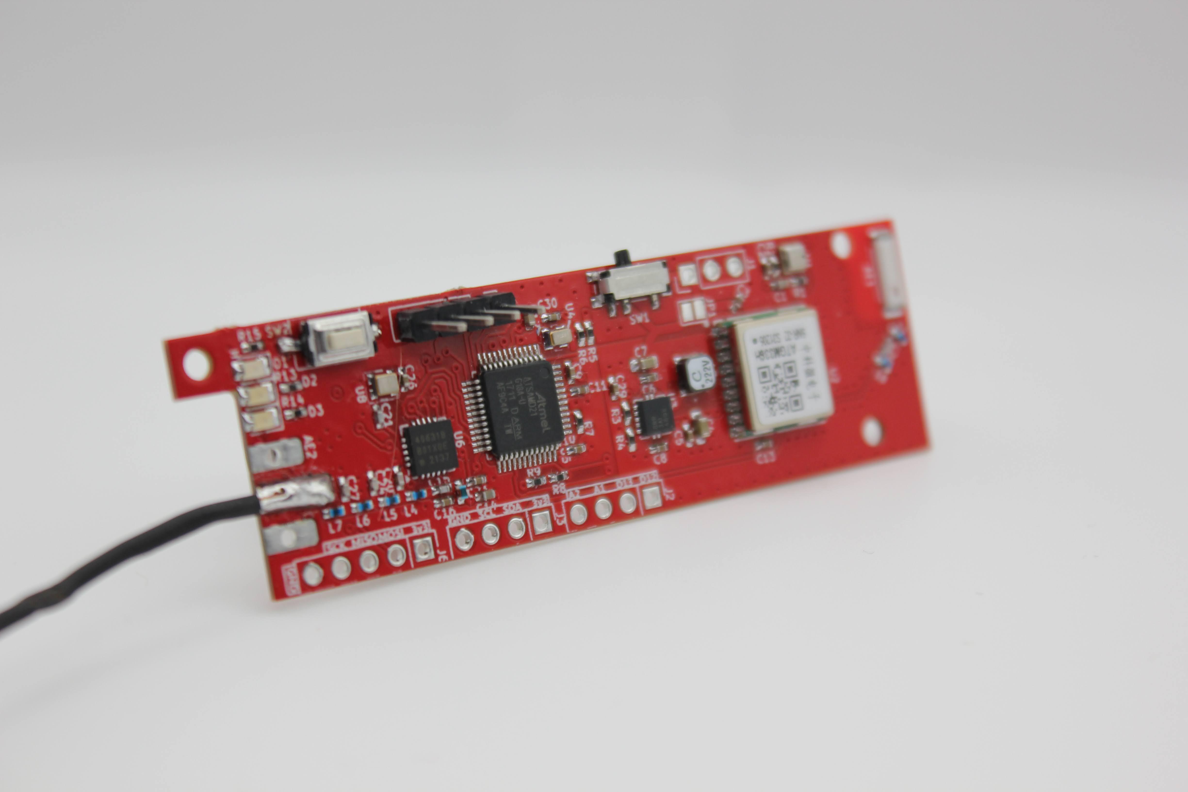
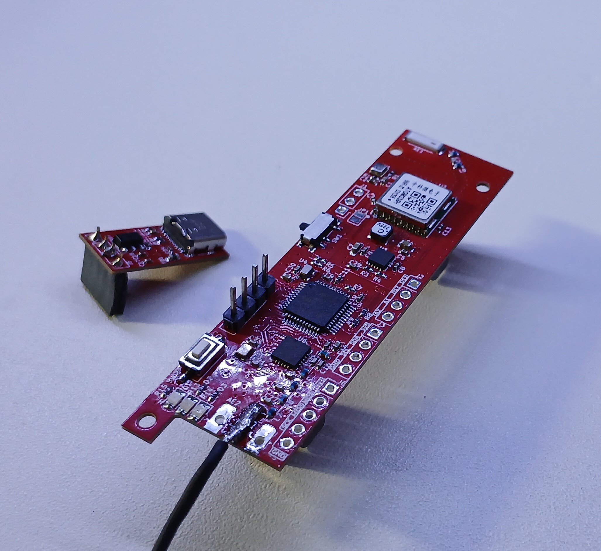 3. To program the board, attach the USB breakout board as shown in the photo. Once the board is programmed, the USB breakout board can be removed for flight.
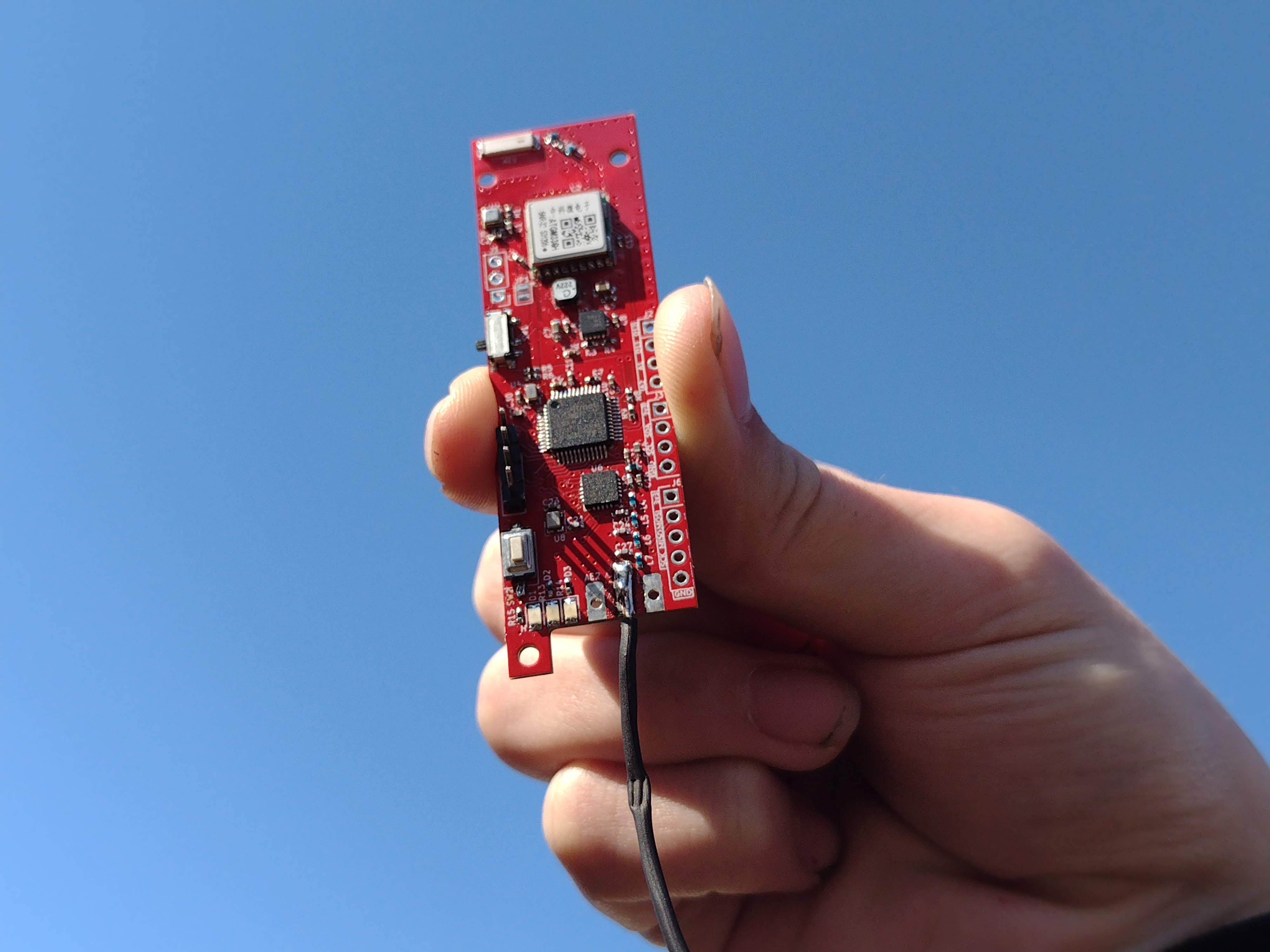
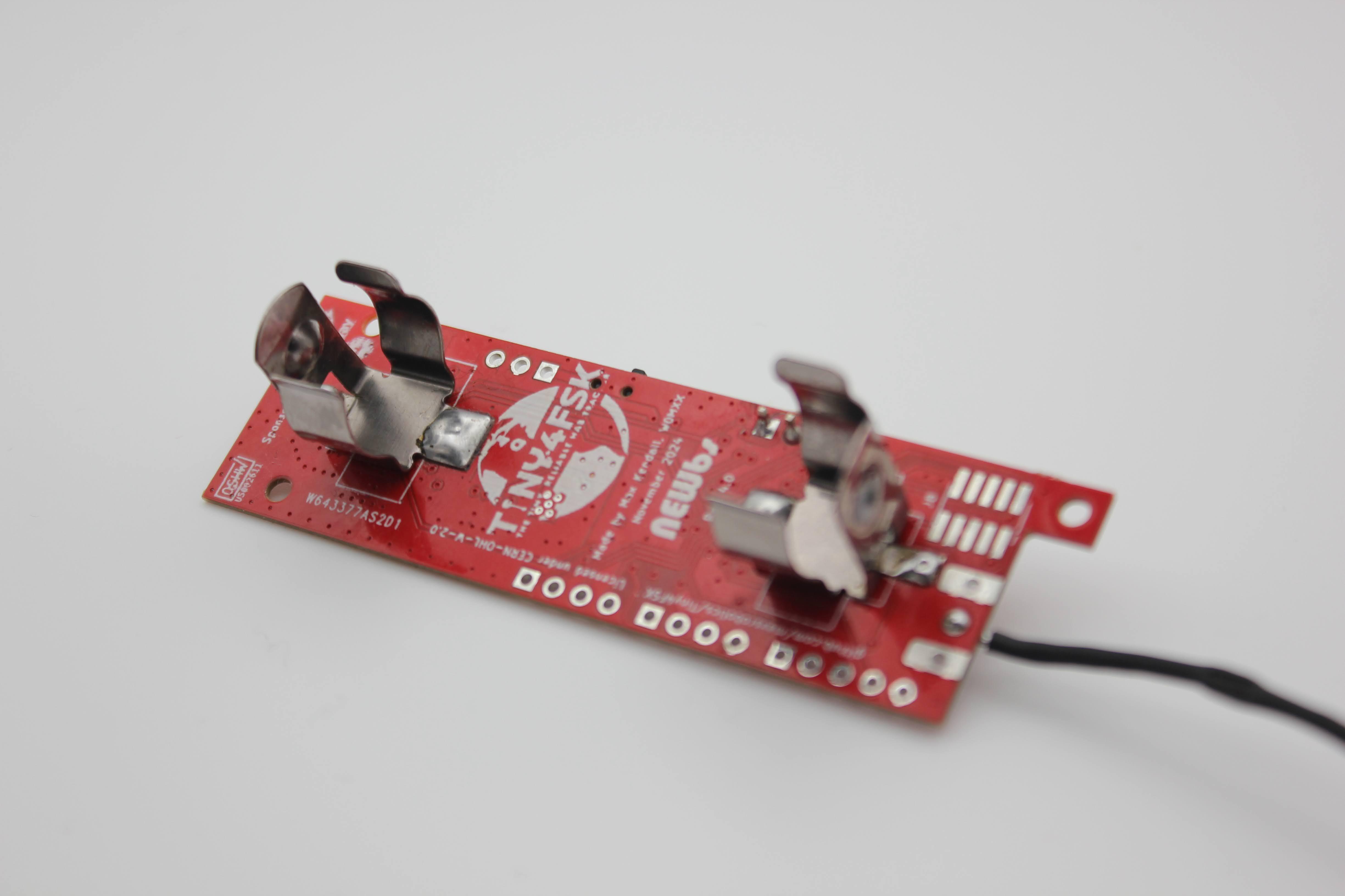
This system relies on the 70cm amateur radio band (420-450 MHz in the US), and requires an amateur radio license, issued by the FCC, to operate. A pre-cut braided copper monopole is included, optimized to transmit on this frequency. The included antenna is a quarter-wave monopole, meaning that the antenna is just a quarter of the wavelength of the signal, and yet it maintains a good SWR (quantification of how much signal is reflected back into the transmitter). There is a pad that supports a quarter-wave monopole, but also provides grounding pads for a coax connector if alternate antennas wish to be used.
Solder the copper wire onto the center pin of the antenna connector (as depicted below).
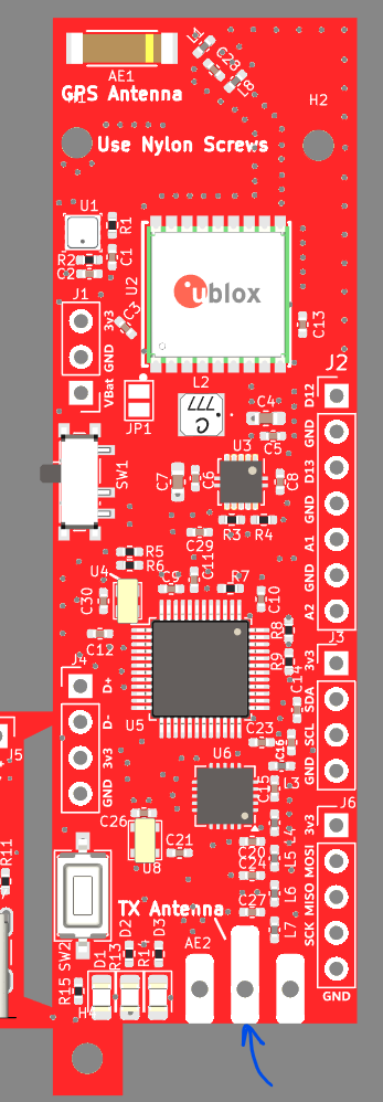
The Tiny4FSK PCB has many configurable operating modes, pins and power sources. This section will outline these parts of the PCB.
The PCB contains one jumper, JP1.
There are also two switches/buttons, SW1 and SW2.
There are two antenna pads, AE1 and AE2.
Now that you've got all the hardware set up, time for programming!
This project is based on the Arduino IDE workflow. Below steps outline steps necessary to install Arduino IDE and configure it for the SAMD microcontroller.
Optional - The SAMD goes to sleep to save power. To achieve proper sleep, some edits to the SAMD core are necessary. To locate the wiring.c file on your computer, follow this guide.
Windows: C:/Users/[YOUR USER]/AppData/Local/Arduino15/packages/arduino/hardware/samd/1.8.14/cores/arduino
Once there, comment out or completely delete the lines shown below:
    // Defining VERY_LOW_POWER breaks Arduino APIs since all pins are considered INPUT at startup
    // However, it really lowers the power consumption by a factor of 20 in low power mode (0.03mA vs 0.6mA)
    #ifndef VERY_LOW_POWER
      // Setup all pins (digital and analog) in INPUT mode (default is nothing)
      for (uint32_t ul = 0 ; ul < NUM_DIGITAL_PINS ; ul++ )
      {
        pinMode( ul, INPUT ) ;
      }
    #endif
Arduino gives you an official warning: "This breaks Arduino APIs since all pins are considered INPUT at startup. However, it really lowers the power consumption by a factor of 20 in low power mode (0.03mA vs 0.6mA)". Testing has shown no adverse effects.
User configuration of this tracker is required. As this system uses amateur radio, you will need at least a Technician's level license (US). Configuration file is located in config.h. Open this file in Arduino IDE. Here are the parameters may need to be changed.
CALLSIGN - Amateur radio callsign. This is required to stay legal!CALLSIGN_WPM - Speed to send the callsign, in morse code.CALLSIGN_INTERVAL - Interval to send the morse code callsign. Maximum interval in the US is 10 minutes.FREQUENCY - This is setting for your preferred TX frequency. The filter is optimized for 70cm radio band.STATUS_LED - Comment out to disable verbose status LEDs on PCB.DEV_MODE - Comment out for flight mode, uncomment during programming. Disables Serial and enables deep sleep modes for lower power consumption.PACKET_INTERVAL - Interval between 4FSK packets. The smaller the interval, the lower the battery life is.OUTPUT_POWER - 0-127. This is the output power of the radio module (suggested to keep at maximum).FLAG_BAD_PACKET - If the latest GPS values are bad, send out all zeroes (for time, position, speed, and altitude)(suggested).QUICK_LOCK - Quick lock mode lowers the output power and increases packet interval while the GPS doesn't have a lock. This helps with desensing the GPS receiver. Values return to previously-defined PACKET_INTERVAL and OUTPUT_POWER upon lock.QUICK_LOCK_POWER - Power level used while the GPS doesn't have a lock. Only applied if QUICK_LOCK mode is enabled.QUICK_LOCK_INTERVAL - Packet interval used while the GPS doesn't have a lock. Only applied if QUICK_LOCK mode is enabled.RECOVERY_MODE - If enabled, the tracker will send updates less frequently when on the ground to save power. Only occurs if the tracker detects it's in a flight.RECOVER_MODE_INTERVAL - Interval to transmit in recovery mode, when on the ground.RECOVERY_MODE_FLIGHT_THRESHOLD - Altitude threshold to consider ourselves in flight, in meters.RECOVERY_MODE_LAND_THRESHOLD - Altitude threshold to consider ourselves on the ground, in meters. Recovery mode will trigger below this altitude.Approximate mapping from the OUTPUT_POWER numeric value to typical output in dBm:
| Value | Approx. dBm |
|---|---|
| 127 | 19 dBm |
| 100 | 18 dBm |
| 80 | 16.5 dBm |
| 60 | 14.5 dBm |
| 40 | 11.4 dBm |
| 20 | 5.6 dBm |
| 0 | -45 dBm |
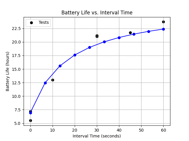
Through a series of battery life tests on ground-level, we've created a graph approximating the battery life with reference to packet interval and transmit power.
These graphs only provide an approximation. Variation will still occur from battery to battery, and we always recommend testing yourself prior to flight and aiming for double the battery life necessary.
At maximum power (127):
All power levels from 0 (no amplifier) to 127 (max power):
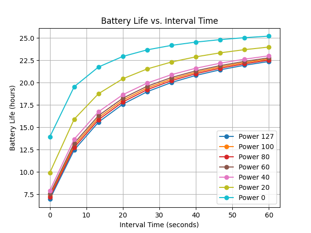
All tests ran with quick lock off and 1x Energizer Ultimate Lithium AA.
Once code configuration is complete, you may plug in a standard data USB-C cable into the breakout board, select the port in Arduino IDE, and select the upload button (marked by an arrow at the top). You should select the Arduino Zero (Native USB Port) as the board name.
Once the code is uploaded, you'll see the green LED pulse briefly to indicate initialization. The behavior of that LED is outlined here. Now you'll need to set up a receive station on either a laptop and an RTL-SDR, Raspberry Pi and RTL-SDR, or any browser-enabled device with an RTL-SDR.
You should start decoding packets transmitted from the board with your configuration parameters. It may take up to 5 minutes to gain a GPS fix, depending on your location.
| Green LED Behavior | Meaning |
|---|---|
| Single 1s pulse | GPS detected / Airborne mode set (single pulse during initialization) |
| Single 0.5s pulse | Packet transmission (packet build / transmit — single short pulse) |
| Off | Idle or deep sleep (no continuous blinking) |
Tiny4FSK now offers compatibility with external sensors by automatically scanning I2C on startup. Some sensors come with the Tiny4FSK General Shield, which can be found on the GitHub Repository. If you have any custom sensors which you would like me to add support for, please raise an issue.
The Revision 4 PCBs have been fabricated and assembled through PCBWay. Their high-quality fabrication and assembly services are truly commendable. I appreciated the ability to choose from many different component suppliers to select the exact components I needed. Additionally, their customer service is incredibly responsive and helpful, and quickly notified me of design issues. I highly recommend PCBWay for any of your PCB prototyping & assembly needs. Thank you, PCBWay, for graciously sponsoring this project!

To ask questions, kindly donate, or even say hi, feel free to contact me at this email: tiny4fsk@gmail.com. Thanks!
This project would not be possible without the following individuals:
And these entities:
Software and Documentation:
Hardware License:
| Qty | Value | Footprint | References |
|---|---|---|---|
| 10 | 100nF | Capacitor_SMD:C_0402_1005Metric | C2, C5, C6, C8, C9, C10, C21, C23, C26, C36 |
| 6 | 1uF | Capacitor_SMD:C_0402_1005Metric | C11, C17, C18, C19, C25, C34 |
| 5 | 10uF | Capacitor_SMD:C_0402_1005Metric | C1, C3, C7, C12, C14 |
| 3 | 330R | Capacitor_SMD:C_0402_1005Metric | R13, R14, R15 |
| 3 | MountingHole | MountingHole:MountingHole_2.2mm_M2 | H1, H2, H4 |
| 2 | 1.8kR | Resistor_SMD:R_0402_1005Metric | R8, R9 |
| 2 | 100kR | Capacitor_SMD:C_0402_1005Metric | R20, R22 |
| 2 | 10kR | Resistor_SMD:R_0402_1005Metric | R7, R10 |
| 2 | 10pF | Capacitor_SMD:C_0402_1005Metric | C20, C24 |
| 2 | 150kR | Capacitor_SMD:C_0402_1005Metric | R21, R23 |
| 2 | 15pF | Capacitor_SMD:C_0402_1005Metric | C13, C22 |
| 2 | 21nH | Inductor_SMD:L_0402_1005Metric | L5, L7 |
| 2 | 5.1kR | Resistor_SMD:R_0402_1005Metric | R5, R6 |
| 1 | 1.3pF | Capacitor_SMD:C_0402_1005Metric | C28 |
| 1 | 100uF | Capacitor_SMD:C_0402_1005Metric | C35 |
| 1 | 13pF | Capacitor_SMD:C_0402_1005Metric | C16 |
| 1 | 1575AT43A0040 | RF_Antenna_Custom:ANT_1575AT_JOT | AE1 |
| 1 | 180kR | Resistor_SMD:R_0402_1005Metric | R4 |
| 1 | 1MR | Resistor_SMD:R_0402_1005Metric | R3 |
| 1 | 2.2pF | Capacitor_SMD:C_0402_1005Metric | C27 |
| 1 | 2.2uH | Inductor_SMD:L_Coilcraft_LPS3010 | L2 |
| 1 | 20nH | Capacitor_SMD:C_0402_1005Metric | L1 |
| 1 | 220nH | Inductor_SMD:L_0402_1005Metric | L3 |
| 1 | 22nH | Inductor_SMD:L_0402_1005Metric | L4 |
| 1 | 22uF | Capacitor_SMD:C_0402_1005Metric | C4 |
| 1 | 26MHz | Crystal:Crystal_SMD_2016-4Pin_2.0x1.6mm | U8 |
| 1 | 3.9pF | Capacitor_SMD:C_0402_1005Metric | C31 |
| 1 | 32.768kHz | Crystal:Crystal_SMD_3215-2Pin_3.2x1.5mm | Y1 |
| 1 | 36.5nH | Inductor_SMD:L_0402_1005Metric | L6 |
| 1 | 51nH | Inductor_SMD:L_0402_1005Metric | L10 |
| 1 | 56nH | Inductor_SMD:L_0402_1005Metric | L9 |
| 1 | 5kR | Resistor_SMD:R_0402_1005Metric | R11 |
| 1 | 9.1pF | Capacitor_SMD:C_0402_1005Metric | C15 |
| 1 | ATGM336H | RF_GPS:ublox_MAX | U11 |
| 1 | ATSAMD21G18A-A | Package_QFP:TQFP-48_7x7mm_P0.5mm | U5 |
| 1 | BK-53 | Battery_Custom:BAT_BK-53 | BT1 |
| 1 | BME280 | Package_LGA:Bosch_LGA-8_2.5x2.5mm_P0.65mm_ClockwisePinNumbering | U1 |
| 1 | ERR_LED | LED_SMD:LED_0603_1608Metric | D2 |
| 1 | ExtPA | TestPoint:TestPoint_Pad_D1.0mm | TP1 |
| 1 | GCT-4105 | Connector_USB:USB_C_Receptacle_GCT_USB4105-xx-A_16P_TopMnt_Horizontal | J7 |
| 1 | GOOD_LED | LED_SMD:LED_0603_1608Metric | D1 |
| 1 | GPIO_ROW | Connector_PinHeader_2.54mm:PinHeader_1x15_P2.54mm_Vertical | J10 |
| 1 | NC | Inductor_SMD:L_0402_1005Metric | L8 |
| 1 | POWER_LED_ENABLE | Jumper:SolderJumper-2_P1.3mm_Bridged_RoundedPad1.0x1.5mm | JP2 |
| 1 | PWR | Button_Switch_SMD:SW_SPDT_PCM12 | SW1 |
| 1 | PWR | Connector_PinHeader_2.54mm:PinHeader_1x06_P2.54mm_Vertical | J2 |
| 1 | PWR_LED | LED_SMD:LED_0603_1608Metric | D3 |
| 1 | RST | Button_Switch_SMD:SW_SPST_TS-1088-xR020 | SW2 |
| 1 | SWD | Connector_Pogo_1.27mm:Pogo_2x05_P1.27mm | J8 |
| 1 | Si4463 | Package_DFN_QFN:QFN-20-1EP_4x4mm_P0.5mm_EP2.6x2.6mm_ThermalVias | U6 |
| 1 | Switch EN | Jumper:SolderJumper-2_P1.3mm_Open_Pad1.0x1.5mm | JP1 |
| 1 | TPS2116DRL | Package_TO_SOT_SMD:SOT-583-8 | U9 |
| 1 | TPS61200DRC | Package_SON:Texas_S-PVSON-N10_ThermalVias | U3 |
| 1 | TX Antenna | Connector_Coaxial:SMA_Samtec_SMA-J-P-H-ST-EM1_EdgeMount | AE2 |
| 1 | USBLC6-2SC6 | Package_TO_SOT_SMD:SOT-23-6 | U10 |
| 1 | XC6210B332MR | Package_TO_SOT_SMD:SOT-23-5 | U7 |
It measures 18 × 63 mm and has 4 copper layers, 1.6 mm thick.
86 parts, built around the ATSAMD21G18A-AU, BME280, TPS61200DRC and SI4463DY. The full list of its parts is on this page, with links to each part's symbol and footprint where PCBKit's library has them.
From the mpkendall/gumstik repository on GitHub, at the commit this page was made from: the board is hardware/Tiny4FSK.kicad_pcb and its schematic hardware/Tiny4FSK.kicad_sch. PCBKit opens the board in the browser, with nothing to install.
Its repository publishes it under the CERN-OHL-W-2.0 licence: you may reuse it on that licence's terms (keep the author's notice, and for a copyleft licence share your changes alike).
New-England-Weather-Balloon-Society/Tiny4FSK
Horus Binary v2 HAB Tracker


hackclub/OnBoard
💡 Join 1,000 teenagers and make your first PCB with a $100 grant!

crnicholson/StratoSoar-MK2
StratoSoar is an engineering project that aims to be able to fly a glider (dropped from a high-altitude balloon), down to any selected coordinates.


mrcha033/hw-codesign
Agentic hardware co-design: brief to KiCad, firmware, 3D review, and explicit fabrication blockers.
