

2 layers20.5 × 15.1 mm

 mpek29/UsbUartBridge
🔌 USB-to-UART bridge for embedded systems
UsbUartBridge is an open-source printed circuit board by mpek29, from the mpek29/UsbUartBridge repository on GitHub. It is a 2-layer board of 50.9 × 17.8 mm with 15 parts on 32 nets, routed with 120 tracks and 12 vias.
It is built around the CP2102, SM04B-SRSS-TB(LF)(SN)(P) and UJ2-MIBH-G-SMT-TR. Its parts include 4 resistors, 4 connectors, 3 capacitors, 3 diodes and 1 IC. It belongs with the interfaces and adapters boards of this library.
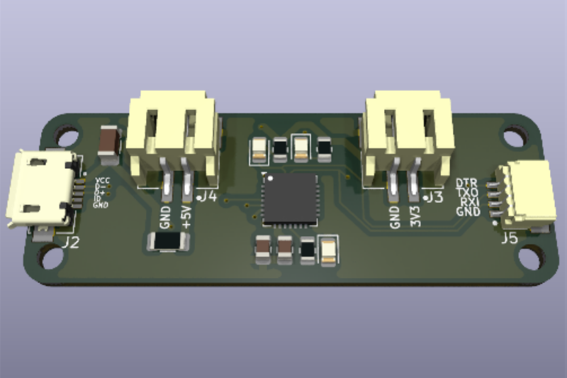
UsbUartBridge is an open-source PCB designed to provide a USB-to-UART bridge for seamless serial communication between a computer and microcontrollers. The board features JST-SH & JST-PH connectors for easy integration into embedded projects, IoT devices, and prototyping setups.
| 🏷️ Feature | 🔍 Description |
|---|---|
| 🔌 USB Interface | Micro-USB (for PC connection) |
| 📡 UART Interface | TX, RX, DTR |
| 🔋 Voltage Options | 3.3V & 5V selectable output |
| 🛠️ Connectivity | JST-SH & JST-PH connectors for easy integration |
| 🔧 Capacitors | Decoupling capacitors for stability |
| 🖥️ PCB Design | Open-source & customizable |
| 🌍 Use Cases | Debugging & Programming microcontrollers, IoT device communication, serial data transfer |
| 📜 Schematic | 🖥️ PCB Layout | 🏗️ 3D |
|---|---|---|
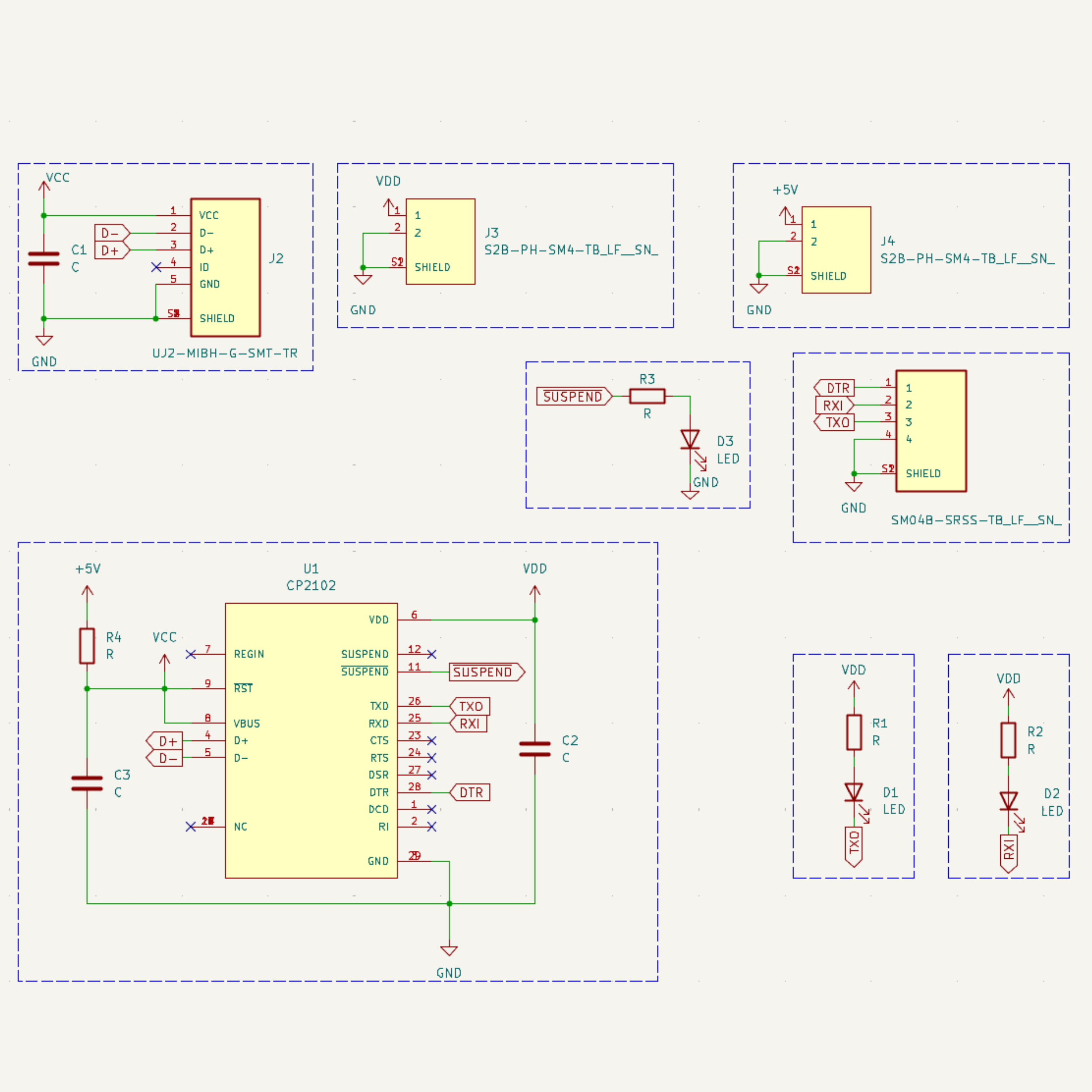 | 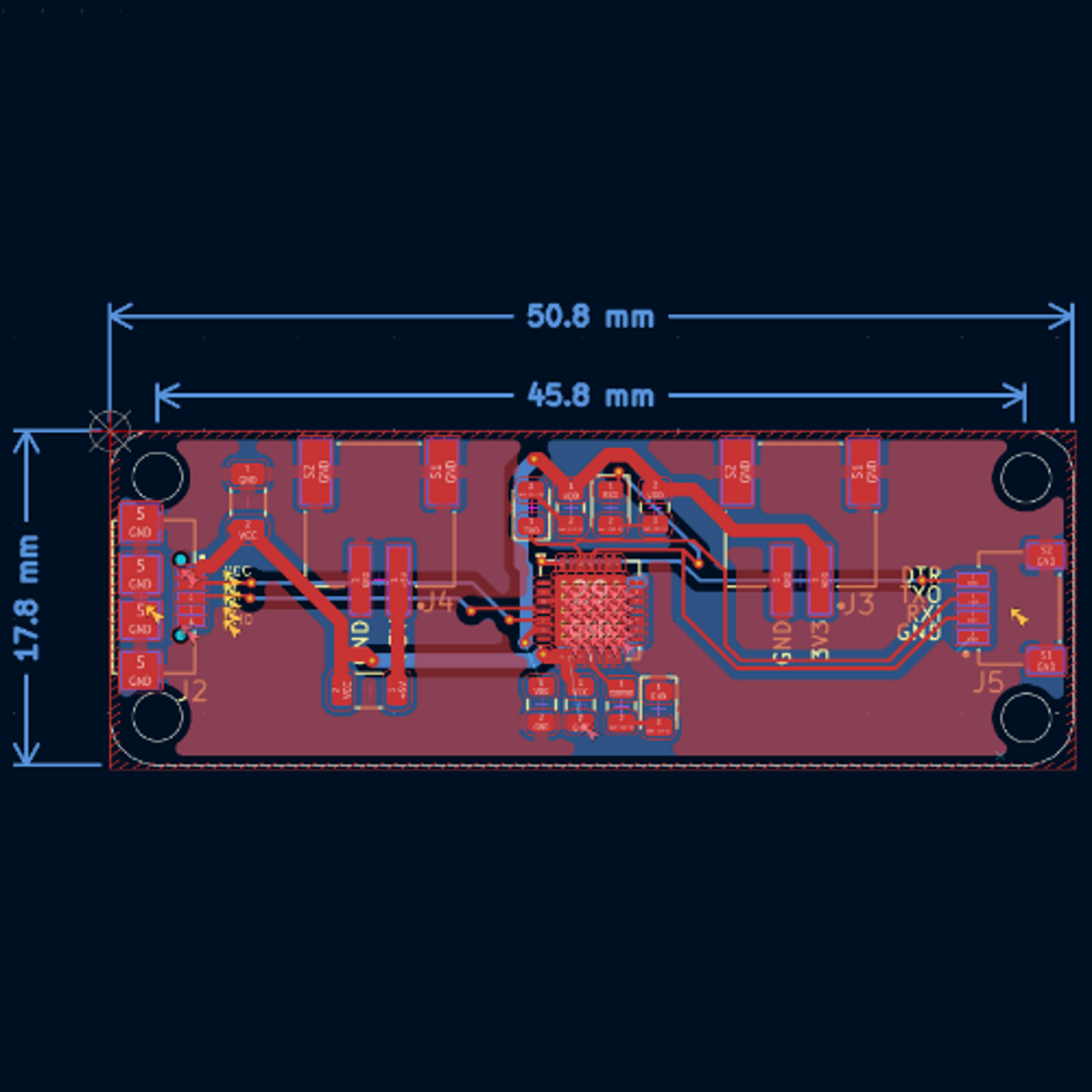 | 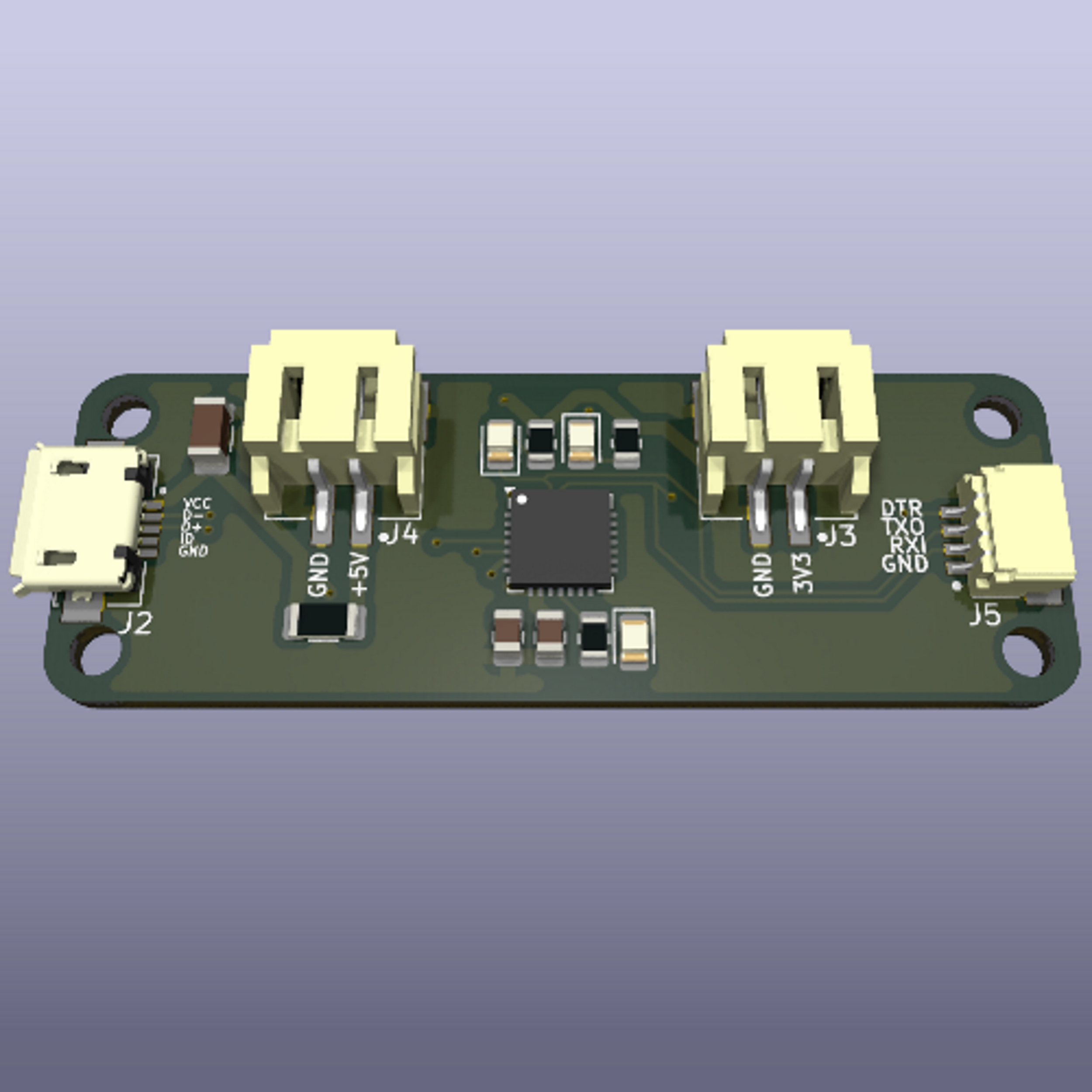 |
This project is open-source. Feel free to use, modify, and contribute! 🚀
| Qty | Value | Footprint | References |
|---|---|---|---|
| 3 | 100nF | Capacitor_SMD:C_0603_1608Metric_Pad1.08x0.95mm_HandSolder | C1, C2, C3 |
| 3 | 1k | Resistor_SMD:R_0402_1005Metric_Pad0.72x0.64mm_HandSolder | R1, R2, R3 |
| 3 | LED | LED_SMD:LED_0805_2012Metric | D1, D2, D3 |
| 2 | S2B-PH-SM4-TB_LF__SN_ | footprints:JST_S2B-PH-SM4-TB_LF__SN_ | J3, J4 |
| 1 | 470 | Resistor_SMD:R_0603_1608Metric_Pad0.98x0.95mm_HandSolder | R4 |
| 1 | CP2102 | Package_DFN_QFN:QFN-28-1EP_5x5mm_P0.5mm_EP3.75x3.75mm_ThermalVias | U1 |
| 1 | SM04B-SRSS-TB_LF__SN_ | footprints:JST_SM04B-SRSS-TB_LF__SN_ | J5 |
| 1 | UJ2-MIBH-G-SMT-TR | footprints:CUI_UJ2-MIBH-G-SMT-TR | J2 |


abzman/esp-IoT-boards
R5v: 1.9K for the red LED, 3.9K for the blue LED

vroland/epdiy-hardware
Hardware design files for EPDiy: https://github.com/vroland/epdiy.

atomic14/esp32-tv-hardware
This is Work In Progress - I'm still working on this.

newaetech/sonata-pcb
Design files and associated documentation for Sonata PCB, part of the Sunburst Project

Oak-Development-Technologies/RPGA-Feather
Home of everything RPGA! From schematics and board files to buildable examples!
It measures 50.9 × 17.8 mm and has 2 copper layers, 1.6 mm thick.
15 parts, built around the CP2102, SM04B-SRSS-TB(LF)(SN)(P) and UJ2-MIBH-G-SMT-TR. The full list of its parts is on this page, with links to each part's symbol and footprint where PCBKit's library has them.
From the mpek29/UsbUartBridge repository on GitHub, at the commit this page was made from: the board is design/UsbUartBridge/UsbUartBridge.kicad_pcb and its schematic design/UsbUartBridge/UsbUartBridge.kicad_sch. PCBKit opens the board in the browser, with nothing to install.
Its repository states no licence, so its author keeps all rights: ask mpek29 before reusing the design.