2 layers28.3 × 39.8 mm
LevelShifter
gusmanb/logicanalyzer
24 channel, 100Msps logic analyzer hardware and software
21 parts5.1kGPL-3.0

 mouse625/Numpad
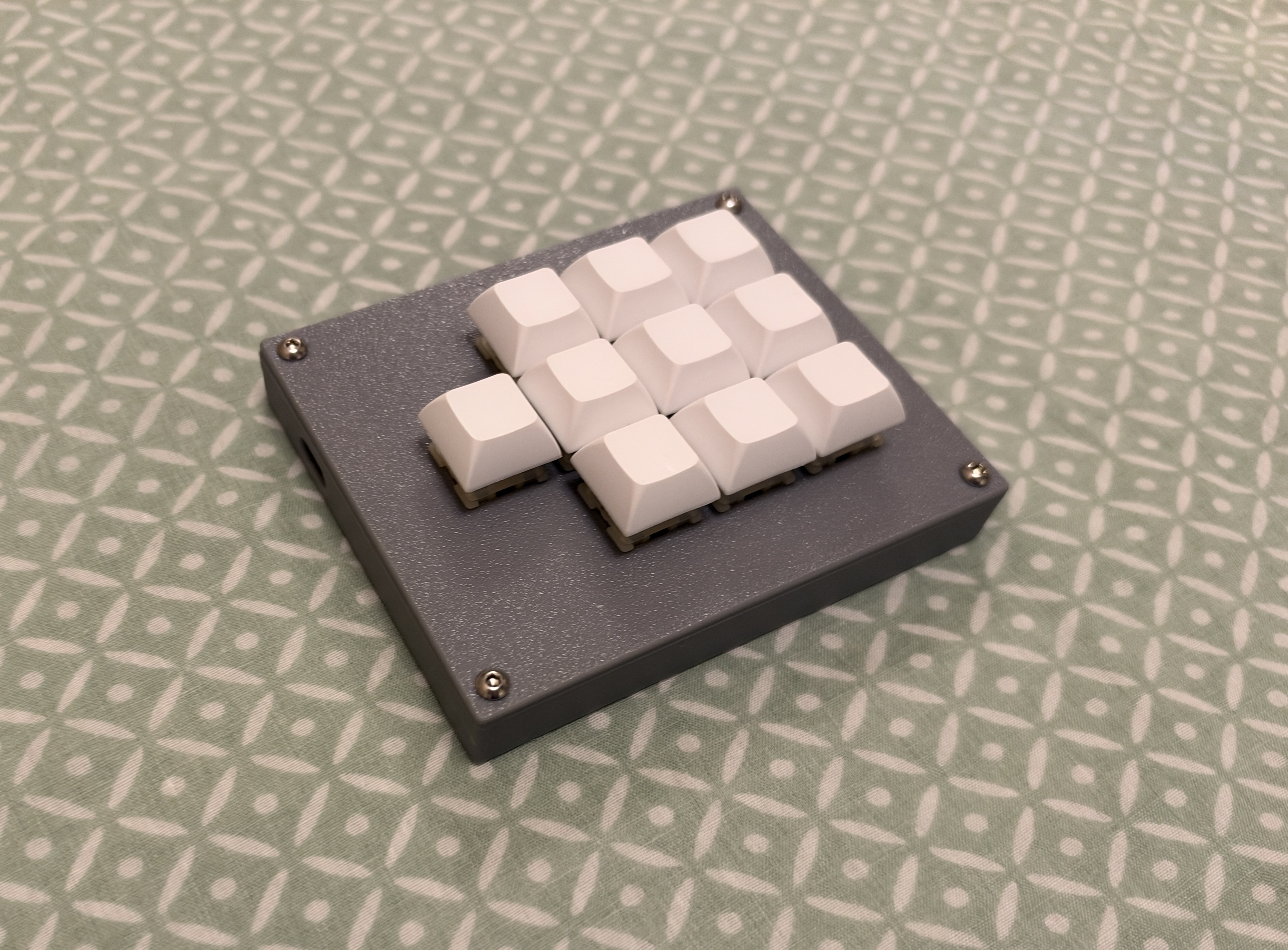
A custom macropad (which functions as guess what, a numpad) created for Hackpad (a mission for Stardance, an event run by Hack Club).
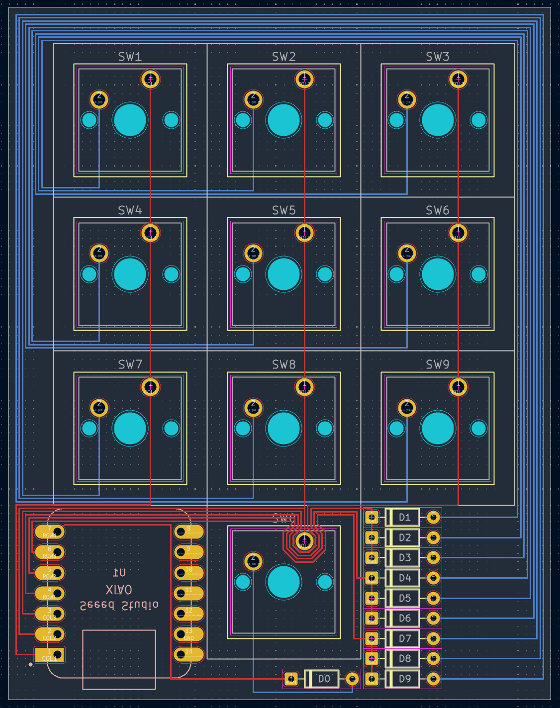
Hackpad is an open-source printed circuit board by mouse625, from the mouse625/Numpad repository on GitHub. It is a 2-layer board of 67.1 × 85.7 mm with 21 parts on 24 nets, routed with 133 tracks and 0 vias.
Its parts include 10 diodes, 10 switches and 1 IC. It belongs with the keyboards and input boards of this library.
self-explanatory, a custom macropad functioning as a numpad.
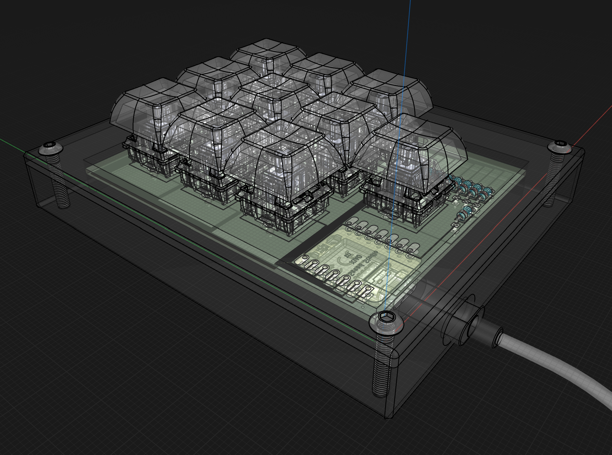
Numpad is a Macropad, a custom sort of mini-keyboard usually designed for faster inputting of hardcoded shortcuts/strings or specific functions. However, this macropad is made as a Numpad accessory for more efficient inputting of numbers.
This project is made possible by Hackpad, a YSWS (you ship we ship) event on making a custom Macropad run by Hack Club.
we all know you love them.
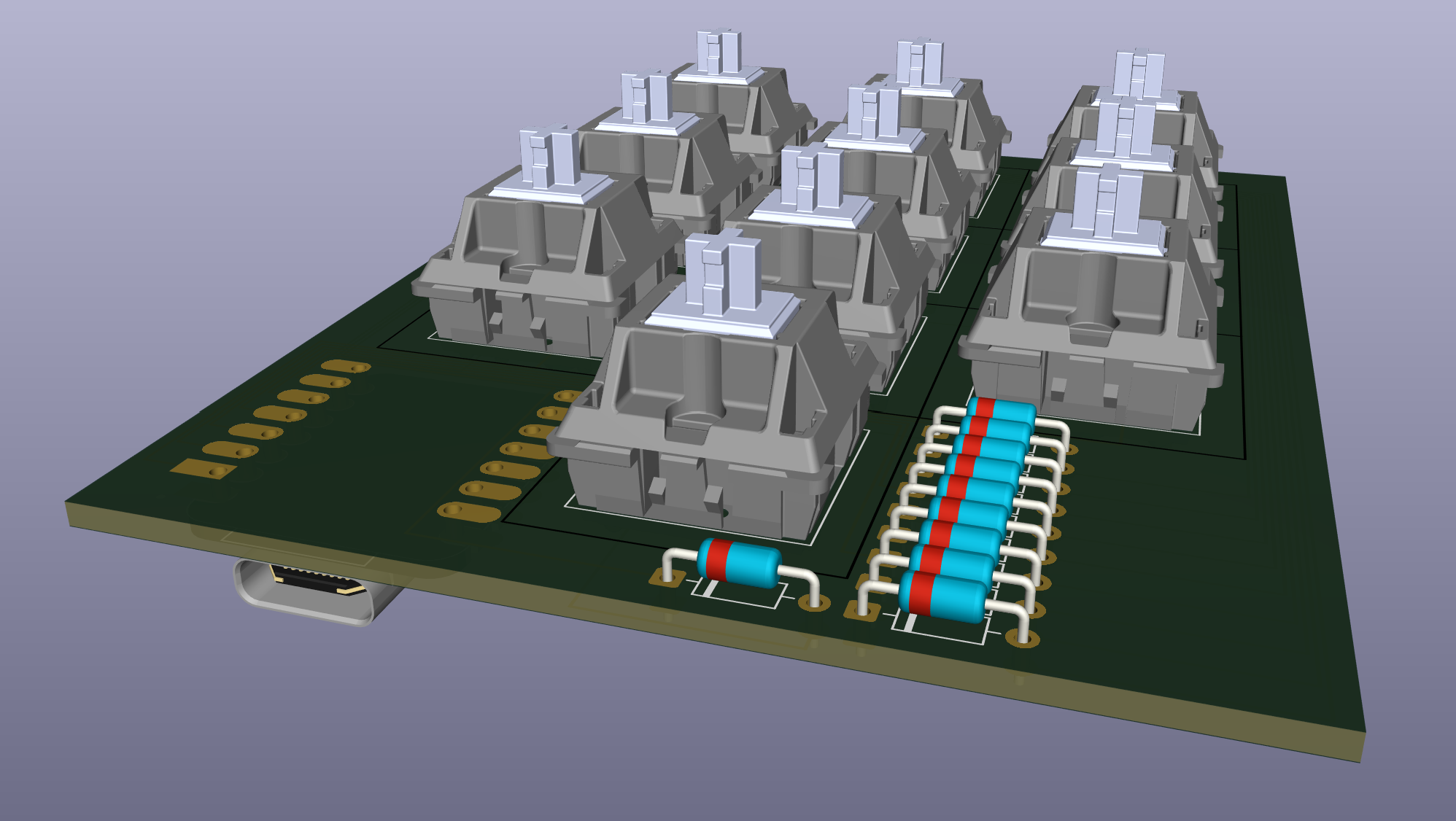
one assembly image (the others are mostly for eye-candy).
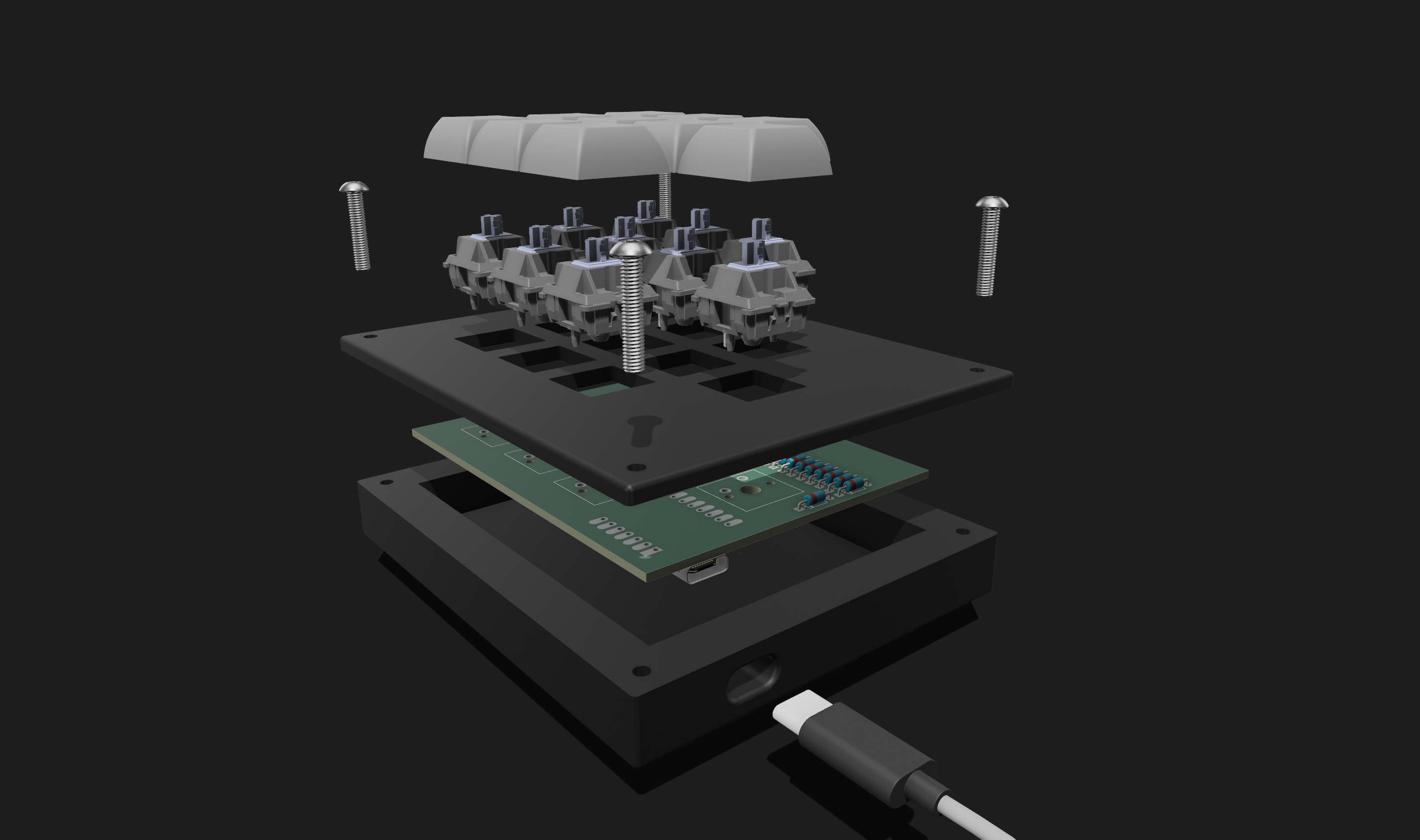
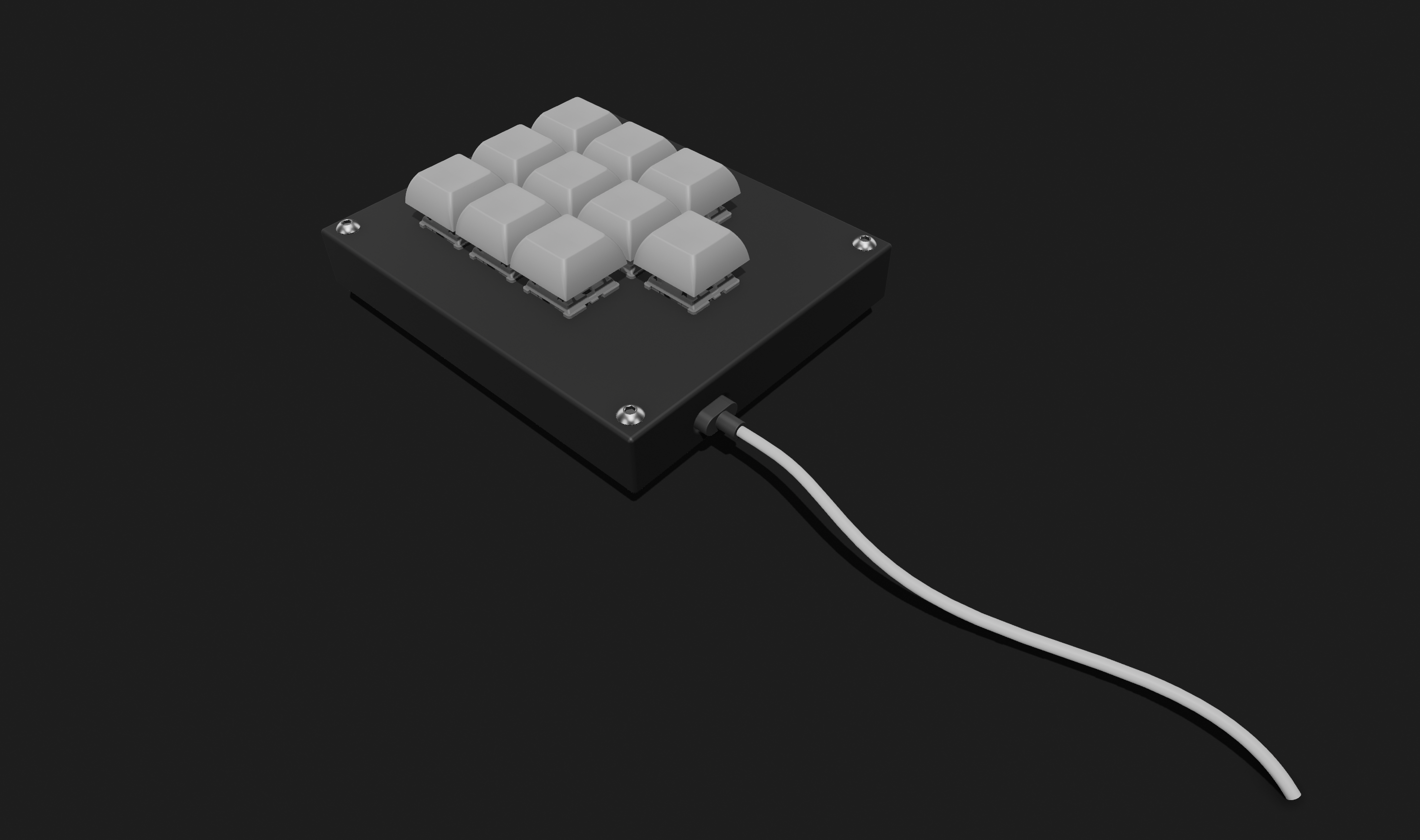
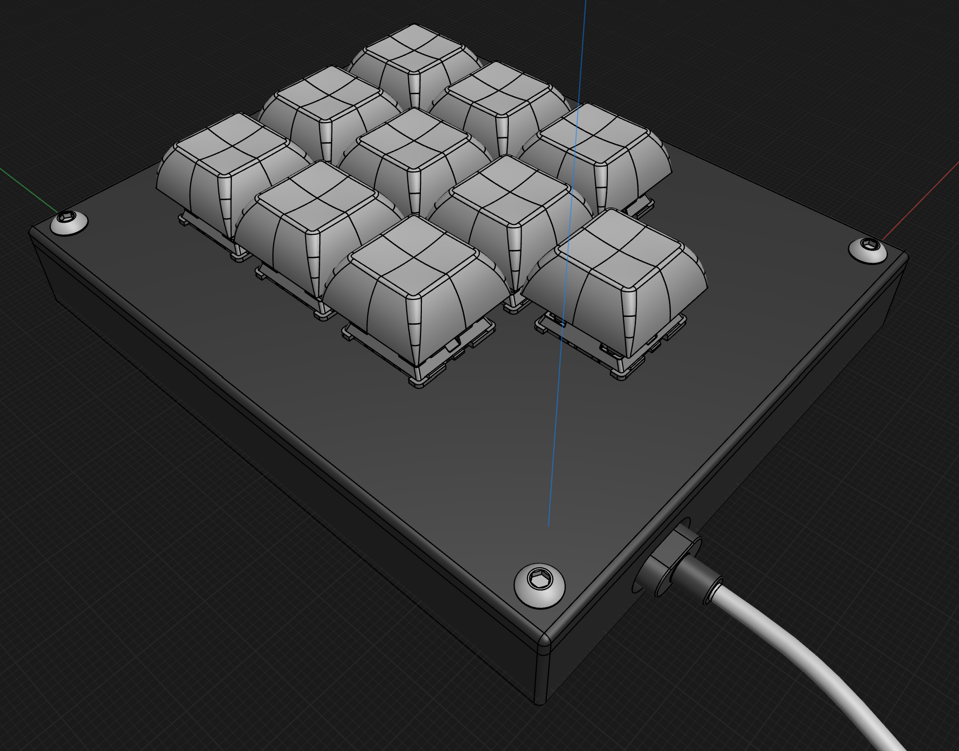
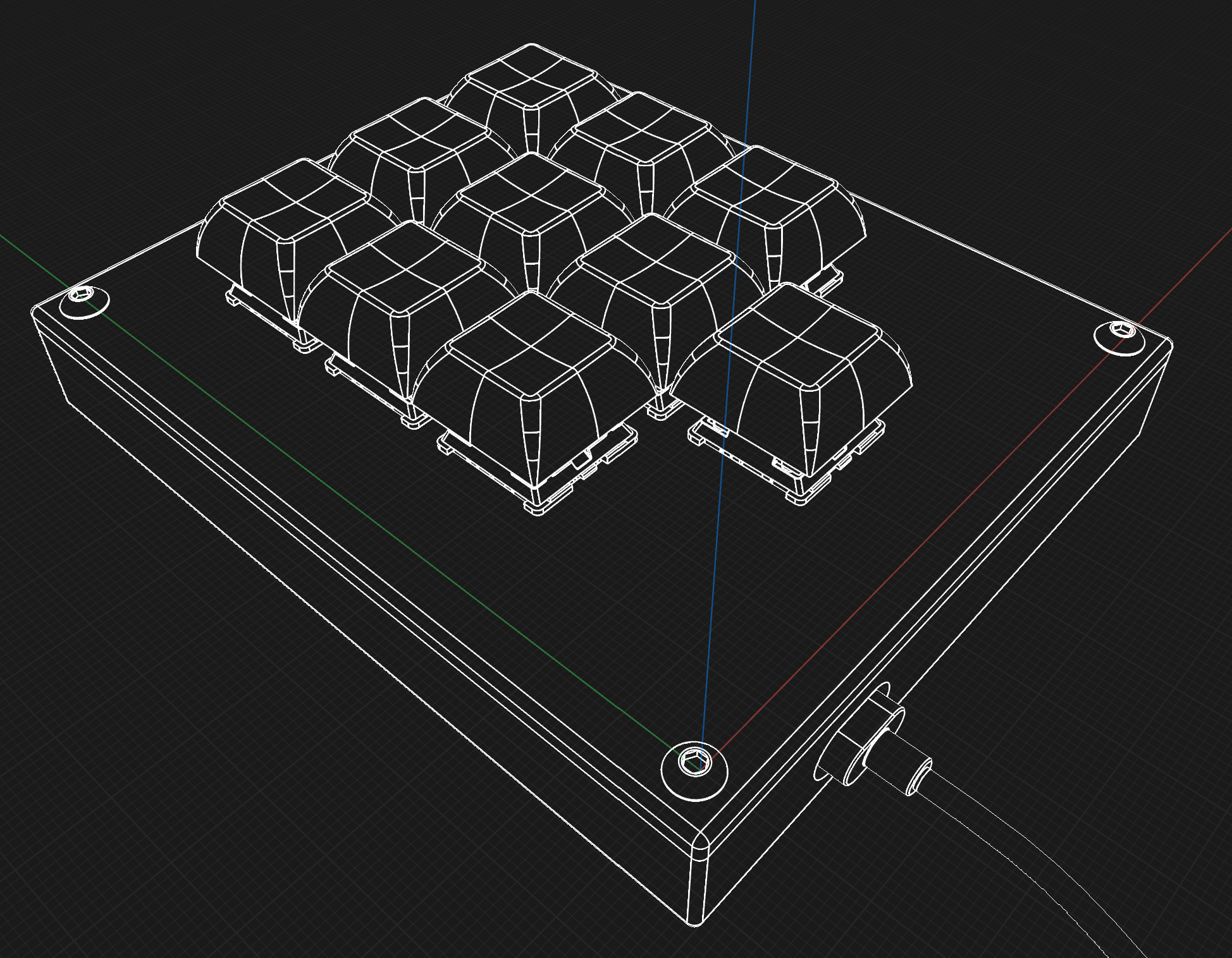
not exactly orthodox "renderings".
the parts.
PCBSeeed XIAO RP20401N4148 DiodesMX-Style switchesDSA KeycapsM3x16mm ScrewsCase
Bottom SectionTop Sectionthe tools (not really part of the BoM but whatever).
Soldering IronSolderWirecuttersScissorsScrewdriverhex key preferable without an obligatory hexFlashing Setup for...flashing
Cable (for power too)Computer3D PrinterFactory for making PCBs
CNC RouterLaser PlotterChemical EtcherPlating SystemSilkscreen PrinterEncephalonPCB, components and case, you'll need to have/obtain access to a soldering iron and some solder, a pair of wire cutters or scissors, a functioning computer and a USB-C cable.XIAO.
cable into the XIAO's port.XIAO can then be held while plugging the other side of the cable into the computer to enter bootloader mode.XIAO should appear as a removable flash drive into which the .uf2 compiled firmware can be dragged and dropped.XIAO can safely be unplugged and is ready to solder.diodes.
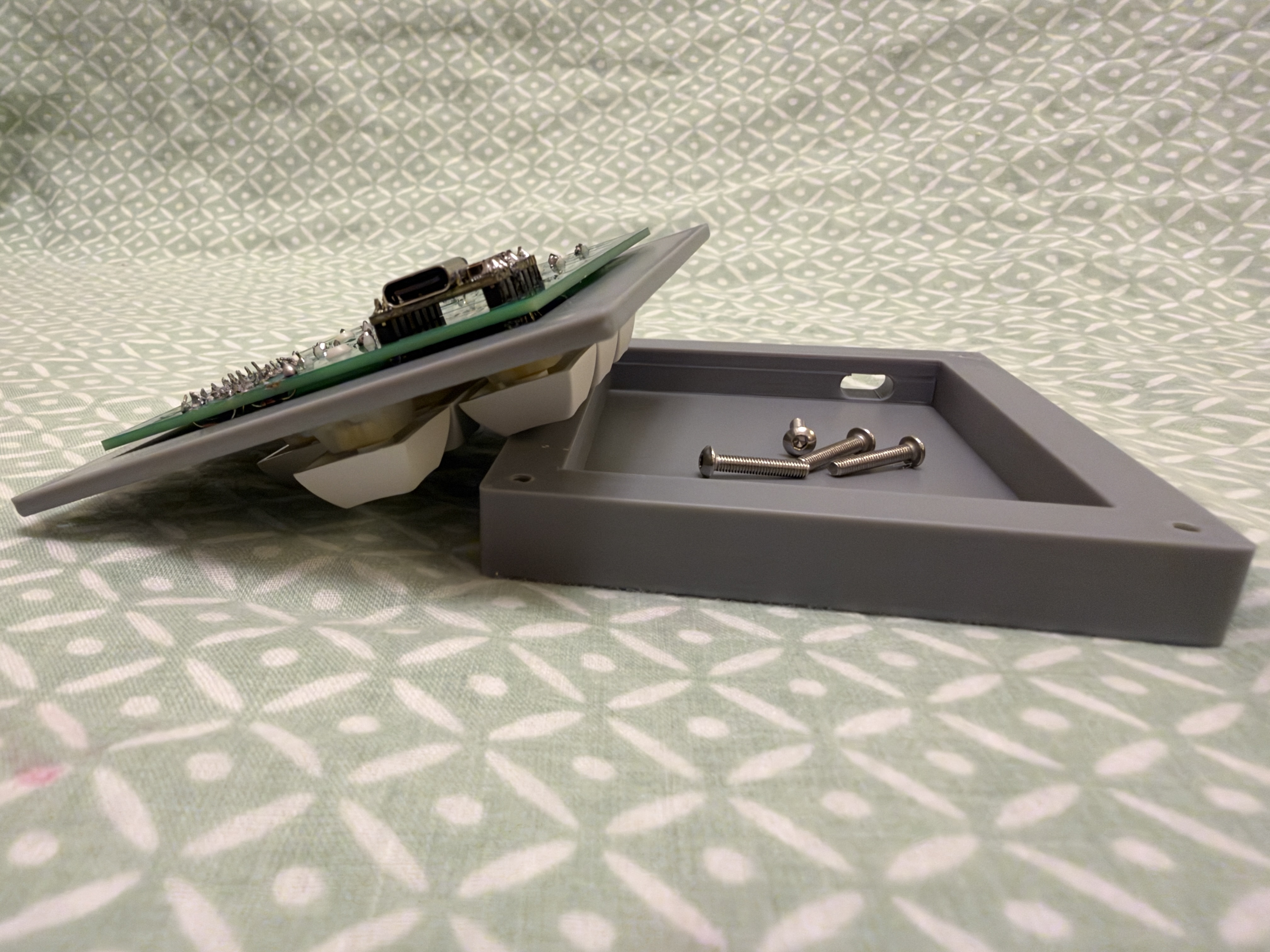
diodes with the stripes on the PCB indicating the direction of the diodes.diodes can then simply be soldered onto the PCB with the soldering iron while slowly feeding solder.wire cutters or scissors (this is highly recommended).XIAO onto the PCB's underside. This should be constantly cross-referenced with the CAD model to avoid any desoldering.keyswitches need to be installed.
PCB. The case plate is REQUIRED to be between the keyswitches and the PCB during this step.keyswitches can now safely be soldered.case plate and main body can now be aligned with the PCB (sandwiched in the middle). A hex key or hex-head screwdriver can then be used to screw 4 M3x16mm screws into their respective locations.keycaps can then be popped into place on your newly-assembled numpad (sadly, it doesn't work magically, so it wasn't really "lastly").numpad and your computer, which acts as power.Do you have any suggestions, fixes, or extensions? If so, you can submit a pull request on this Repository.
Credits to:
HCB for hosting this whole thing
Stardance for running an actual summer event
Hackpad for inspiration on this specific project
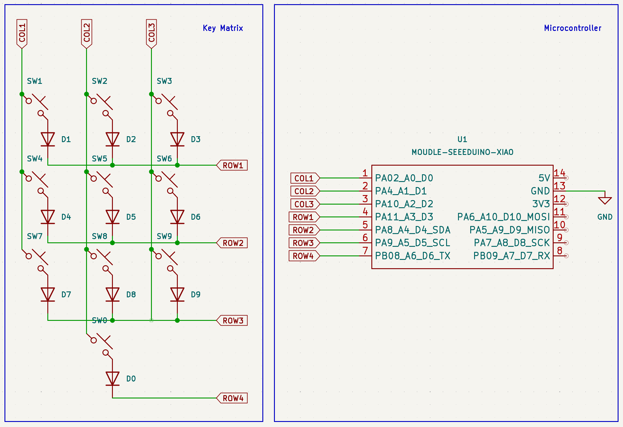
0xmanidev for their schematics made for Spacepad as a reference on Matrix WiringCodeCraftPlugin for making Stream Deck act as a reference for finding the correct DSA keycap models (turns out it was in the parts list that I wrote, so...yeah)cheyao for creating the guidesGrabCAD for their open-source CAD models of various parts
kevin.yu-7 for their models of the Cherry MX Keyswitchesmirac.gulgonul-1 for their model of the Seeed Studio XIAO RP2040chris.barnado-1 for their model of the flexed USB-C Cablezim.cad-1 for their models of the blank white DSA KeycapsMcMaster-Carr for their huge library of various models, most importantly the M3x16 screwsShapr3D, VSCode and KiCad for making the CAD section of all of this possibleGoogle for acting as a universal search engine for all of my dumb queriesThis project uses the MIT License stating that the project is open source and free for anyone to use or develop. For more info, navigate to the LICENSE.md file.
Copyright © 2025 Numpad
| Qty | Value | Footprint | References |
|---|---|---|---|
| 10 | 1N4148 | Diode_THT:D_DO-35_SOD27_P7.62mm_Horizontal | D0, D1, D2, D3, D4, D5, D6, D7, D8, D9 |
| 10 | SW_Push_45deg | Button_Switch_Keyboard:SW_Cherry_MX_1.00u_PCB | SW0, SW1, SW2, SW3, SW4, SW5, SW6, SW7, SW8, SW9 |
| 1 | MOUDLE-SEEEDUINO-XIAO | XIAO:XIAO-Generic-Hybrid-14P-2.54-21X17.8MM | U1 |
It measures 67.1 × 85.7 mm and has 2 copper layers, 1.6 mm thick.
21 parts. The full list of its parts is on this page, with links to each part's symbol and footprint where PCBKit's library has them.
From the mouse625/Numpad repository on GitHub, at the commit this page was made from: the board is source/PCB/hackpad.kicad_pcb and its schematic source/PCB/hackpad.kicad_sch. PCBKit opens the board in the browser, with nothing to install.
Its repository states no licence, so its author keeps all rights: ask mouse625 before reusing the design.
gusmanb/logicanalyzer
24 channel, 100Msps logic analyzer hardware and software

mntmn/amiga2000-gfxcard
MNT VA2000, an Open Source Amiga 2/3/4000 Graphics Card (Zorro II/III), written in Verilog


hackclub/OnBoard
💡 Join 1,000 teenagers and make your first PCB with a $100 grant!

drandyhaas/KiCadRoutingTools
A set of Python/Rust tools to aid routing in KiCad

Arrow-air/project-quiver
Project Quiver documentation, designs, and project artifacts.

