
2 layers68.8 × 53.6 mm
Relatively Universal ROM Programmer
AndersBNielsen/Relatively-Universal-ROM-Programmer
Hardware to program W27C512 EEPROM or any 24/28/32 pin ROM requiring from 5V to 27V programming voltage.
149 parts257GPL-3.0

 motty-mio2/Klask_PCB
This repository contains the KiCad project files for Klask PCB, a custom Arduino Uno R3 shield designed to control stepper motors and limit switches for manipulating a Klask board game.
Klask PCB is an open-source printed circuit board by motty-mio2, from the motty-mio2/Klask_PCB repository on GitHub, published under the CC-BY-SA-4.0 licence. It is a 2-layer board of 69.1 × 53.8 mm with 18 parts on 46 nets, routed with 113 tracks and 25 vias.
It is built around the ARDUINO UNO R3. Its parts include 5 connectors, 4 capacitors, 3 resistors, 2 switches and 1 diode. It belongs with the AVR (ATmega, ATtiny) boards of this library.
This repository contains the KiCad project files for Klask PCB, a custom Arduino Uno R3 shield designed to control stepper motors and limit switches for manipulating a Klask board game.
Klask PCB is a hardware interface designed to automate or robotize the board game "Klask". It uses stepper motors to move the game magnets under the board.
The shield drives two stepper motors (X and Y axes) using Pololu-style DRV8825 stepper driver modules and processes signals from homing limit switches to align the axes. Additionally, it integrates a power sense circuit to detect external 12V supply and is powered efficiently via a USB-PD Trigger Module.
D10 pin.Below is the list of components required to assemble the Klask PCB.
| Component | Designator | Qty | Description / Footprint |
|---|---|---|---|
| DRV8825 Stepper Driver Module | A1, A2 | 2 | Pololu Breakout board style stepper driver |
| Arduino UNO R3 | A3 | 1 | Microcontroller board (acts as base) |
| USB-PD Trigger Module | — | 1 | Set to 12V output mode |
| 10-pin Pin Header | — | 1 | 2.54mm pitch (for Arduino Digital High header) |
| 8-pin Pin Header | — | 1 | 2.54mm pitch (for Arduino Digital Low header) |
| 8-pin Pin Socket | — | 4 | 2.54mm pitch (sockets for DRV8825 modules) |
| LED | D1 | 1 | 3mm THT LED (Power/12V Status Indicator) |
| 2.54mm Terminal Block | J1, J2, J3, J4, J5, SW4, SW5 | 7 | XY308-2.54-2P (For MotXA, MotXB, MotYA, MotYB, 12V, SWX, SWY) |
| 510 Ω Resistor | R1 | 1 | THT Resistor (LED current limiting) |
| 180 Ω Resistor | R2 | 1 | THT Resistor (Power sensing voltage divider) |
| 0.1 µF Capacitor | C1 | 1 | Ceramic Capacitor THT (Power sense noise filter) |
| 100 µF Capacitor | C3, C4 | 2 | Electrolytic Capacitor THT (Motor power decoupling) |
Note: SW2 (SW_A) and SW3 (SW_B) are present on the PCB layout for potential UI expansion but are not populated in this build.
The Arduino Uno R3 digital pins are mapped to the stepper drivers, limit switches, and power sense circuit as follows:
| Signal Name | Arduino Uno Pin | DRV8825 Pin | Description |
|---|---|---|---|
/MX_STEP | D8 | STEP (A1) | X-axis step control pulse |
/MX_DIR | D9 | DIR (A1) | X-axis rotation direction |
/MY_STEP | D4 | STEP (A2) | Y-axis step control pulse |
/MY_DIR | D5 | DIR (A2) | Y-axis rotation direction |
/nEN | D3 | ~{RST}, ~{SLP} (A1, A2) | Driver enable (Reset / Sleep control) |
/M0 | D0 / RX | M0 (A1, A2) | Microstep configuration bit 0 |
/M1 | D1 / TX | M1 (A1, A2) | Microstep configuration bit 1 |
/M2 | D2 | M2 (A1, A2) | Microstep configuration bit 2 |
| Signal Name | Arduino Uno Pin | PCB Connector | Description |
|---|---|---|---|
/SW_X | A5 (Digital I/O) | SW4 | X-axis homing limit switch (Active Low) |
/SW_Y | A4 (Digital I/O) | SW5 | Y-axis homing limit switch (Active Low) |
GND | GND | SW4, SW5 | Common Ground for switches |
| Signal Name | Arduino Uno Pin | Related Parts | Description |
|---|---|---|---|
/A0 | D10 | D1, R1, R2, C1 | Input pin to sense if 12V is connected (HIGH = 12V Present) |
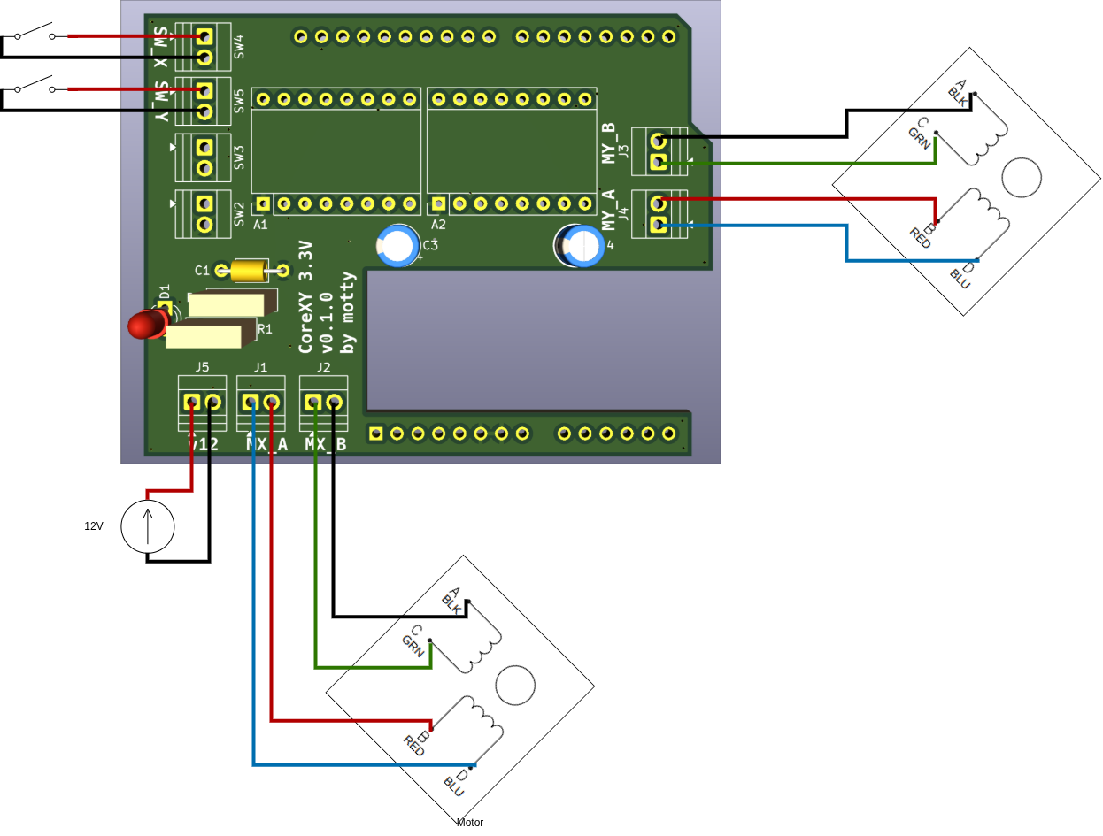
J5 (12V Input): Connect the 12V and GND outputs from the USB-PD Trigger Module.J1 & J2: Connect to the X-axis stepper motor coils (Phase A to J1, Phase B to J2).J3 & J4: Connect to the Y-axis stepper motor coils (Phase A to J3, Phase B to J4).SW4 & SW5: Connect to the X-axis and Y-axis limit switches.D1, R1, R2, C1) and decoupling capacitors (C3, C4).This project is licensed under the CC BY-SA 4.0 (Creative Commons Attribution-ShareAlike 4.0 International) license. Feel free to share, copy, and modify, provided appropriate credit is given and any derivative works are distributed under the same license.
| Qty | Value | Footprint | References |
|---|---|---|---|
| 5 | Conn_01x02_Socket | TerminalBlock:TerminalBlock_Xinya_XY308-2.54-2P_1x02_P2.54mm_Horizontal | J1, J2, J3, J4, J5 |
| 3 | 0.1u | Capacitor_THT:C_Axial_L3.8mm_D2.6mm_P7.50mm_Horizontal | C1, C2, C3 |
| 2 | SW_Push | TerminalBlock:TerminalBlock_Xinya_XY308-2.54-2P_1x02_P2.54mm_Horizontal | SW1, SW2 |
| 1 | 100u | Capacitor_THT:CP_Radial_D5.0mm_P2.50mm | C4 |
| 1 | 180 | Resistor_THT:R_Box_L8.4mm_W2.5mm_P5.08mm | R3 |
| 1 | 1k | Resistor_THT:R_Box_L8.4mm_W2.5mm_P5.08mm | R1 |
| 1 | 510 | Resistor_THT:R_Box_L8.4mm_W2.5mm_P5.08mm | R2 |
| 1 | Arduino_UNO_R3 | Module:Arduino_UNO_R3 | A1 |
| 1 | Breakout_TMC2209 | RoboKlask:TMC2209 | A2 |
| 1 | LED | LED_THT:LED_D3.0mm | D1 |
| 1 | Pololu_Breakout_DRV8825 | RoboKlask:TMC2209 | A3 |
AndersBNielsen/Relatively-Universal-ROM-Programmer
Hardware to program W27C512 EEPROM or any 24/28/32 pin ROM requiring from 5V to 27V programming voltage.

AlanFord/self-balancing-stick
Dual Axis Reaction Wheel Inverted Pendulum

Edging-Machines/Edging-Machines
This repository is intended to contain as much information as possible about building, designing, prototyping, and using automated edging machines.

PedroCNeves/AC_ChargingStation
A learning project to create an EV AC Charging station based on an Arduino Uno

jonsag/arduTester
An arduino component tester based on https://create.arduino.cc/projecthub/plouc68000/ardutester-v1-13-the-arduino-uno-transistor-tester-dbafb4


ICRS/101
The all-new open source Robotics 101 course from ICRS. It's specifically designed to be run in hackspaces, after school clubs and university societies.

It measures 69.1 × 53.8 mm and has 2 copper layers, 1.6 mm thick.
18 parts, built around the ARDUINO UNO R3. The full list of its parts is on this page, with links to each part's symbol and footprint where PCBKit's library has them.
From the motty-mio2/Klask_PCB repository on GitHub, at the commit this page was made from: the board is Klask_PCB.kicad_pcb and its schematic Klask_PCB.kicad_sch. PCBKit opens the board in the browser, with nothing to install.
Its repository publishes it under the CC-BY-SA-4.0 licence: you may reuse it on that licence's terms (keep the author's notice, and for a copyleft licence share your changes alike).