4 layers64.5 × 60 mm
 Morphdust/microscope_camera_pcb
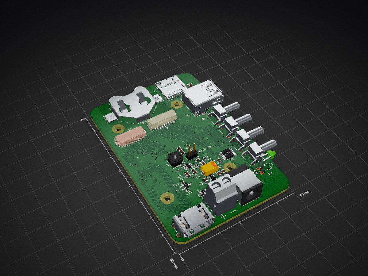
The carrier PCB for CM5 to sit onto and interface to a Pi HQ camera
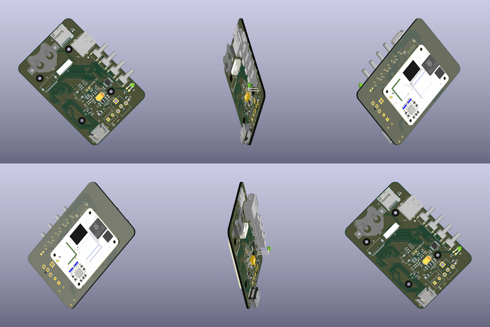
Microscope camera pcb is an open-source printed circuit board by Morphdust, from the Morphdust/microscope_camera_pcb repository on GitHub. It is a 4-layer board of 60 × 90 mm with 44 parts on 170 nets, routed with 854 tracks and 155 vias.
It is built around the 74AHCV17APWJ, AP22653W6 and RT9742SNGV. Its parts include 17 capacitors, 7 connectors, 5 resistors, 4 ICs and 4 switches. It belongs with the computers and single-board computers and interfaces and adapters boards and the Raspberry Pi (Linux) boards of this library.


A carrier PCB for the Raspberry Pi CM5, designed to interface with a Pi HQ camera via CSI for use as a microscope camera.
| Qty | Value | Footprint | References |
|---|---|---|---|
| 4 | 10u | Capacitor_SMD:C_0805_2012Metric | C1, C2, C7, C8 |
| 3 | 10uF | Capacitor_SMD:C_0603_1608Metric_Pad1.08x0.95mm_HandSolder | C4, C5, C6 |
| 2 | 100n | Capacitor_SMD:C_0402_1005Metric | C12, C13 |
| 2 | 100nF | Capacitor_SMD:C_0603_1608Metric_Pad1.08x0.95mm_HandSolder | C9, C16 |
| 2 | 22u | Capacitor_SMD:C_0603_1608Metric_Pad1.08x0.95mm_HandSolder | C11, C14 |
| 2 | SB120 | Diode_SMD:D_1206_3216Metric | D1, D3 |
| 1 | 0.1u | Capacitor_SMD:C_0603_1608Metric_Pad1.08x0.95mm_HandSolder | C17 |
| 1 | 0.1uF | Capacitor_SMD:C_0603_1608Metric_Pad1.08x0.95mm_HandSolder | C10 |
| 1 | 100k | Resistor_SMD:R_0603_1608Metric | R3 |
| 1 | 100uF | Capacitor_Tantalum_SMD:CP_EIA-7343-31_Kemet-D | C3 |
| 1 | 13.3k | Resistor_SMD:R_0603_1608Metric | R4 |
| 1 | 15k | Resistor_SMD:R_0603_1608Metric | R12 |
| 1 | 15u | Inductor_SMD:L_6.3x6.3_H3 | L1 |
| 1 | 1k | Resistor_SMD:R_0603_1608Metric | R1 |
| 1 | 49.9R | Resistor_SMD:R_0603_1608Metric | R2 |
| 1 | 74AHCV17APW | Package_SO:TSSOP-14_4.4x5mm_P0.65mm | U3 |
| 1 | 75pF | Capacitor_SMD:C_0603_1608Metric_Pad1.08x0.95mm_HandSolder | C15 |
| 1 | AP22653W6 | Package_TO_SOT_SMD:SOT-23-6 | U6 |
| 1 | Barrel_Jack_MountingPin | Connector_BarrelJack:BarrelJack_CUI_PJ-063AH_Horizontal_CircularHoles | J4 |
| 1 | Battery_Cell | Battery:BatteryHolder_Multicomp_BC-2001_1x2032 | BT1 |
| 1 | ComputeModule5-CM5 | CM5IO:Raspberry-Pi-5-Compute-Module | Module1 |
| 1 | Conn_01x09_Socket | Connector_JST:JST_GH_SM09B-GHS-TB_1x09-1MP_P1.25mm_Horizontal | J7 |
| 1 | Conn_01x22_Female | CM5IO:Hirose_FH12-22S-0.5SH_1x22-1MP_P0.50mm_Horizontal | J5 |
| 1 | Disable 5V | Connector_PinHeader_2.54mm:PinHeader_1x02_P2.54mm_Vertical | JP1 |
| 1 | HDMI_D_1.4 | Connector_Video:HDMI_A_Amphenol_10029449-x01xLF_Horizontal | J1 |
| 1 | LED Green | LED_THT:LED_D1.8mm_W1.8mm_H2.4mm_Horizontal_O3.81mm_Z8.2mm | D2 |
| 1 | Micro_SD_Card_Det_Hirose_DM3AT | CM5IO:SDCARD_MOLEX_503398-1892 | J3 |
| 1 | Misc Button 0 | CM5IO:SW2_1825027-G_TEC | SW4 |
| 1 | Misc Button 1 | CM5IO:SW2_1825027-G_TEC | SW3 |
| 1 | Picture Button | CM5IO:SW2_1825027-G_TEC | SW1 |
| 1 | RT9742SNGV | Package_TO_SOT_SMD:TSOT-23_HandSoldering | U1 |
| 1 | Screw_Terminal_01x02 | TerminalBlock_MetzConnect:TerminalBlock_MetzConnect_Type011_RT05502HBLC_1x02_P5.00mm_Horizontal | J8 |
| 1 | TPS54202x | CM5IO:DDC0006A-IPC_A | U2 |
| 1 | USB3_A | CM5IO:CONN_484050003_MOL | J2 |
| 1 | WPS Button | CM5IO:SW2_1825027-G_TEC | SW2 |
It measures 60 × 90 mm and has 4 copper layers, 1.6 mm thick.
44 parts, built around the 74AHCV17APWJ, AP22653W6 and RT9742SNGV. The full list of its parts is on this page, with links to each part's symbol and footprint where PCBKit's library has them.
From the Morphdust/microscope_camera_pcb repository on GitHub, at the commit this page was made from: the board is microscope_camera_pcb.kicad_pcb and its schematic RP-008099-DD-1-CM5 IO Board, revision 2, KiCAD files./CM5IO.kicad_sch. PCBKit opens the board in the browser, with nothing to install.
Its repository states no licence, so its author keeps all rights: ask Morphdust before reusing the design.

chanulee/lovelace-ruler
LOVELACE PCB ruler: 55x25 mm reference ruler, KiCad + Figma silkscreen

sanctuary-systems-com/rpi-cm5io-mini-itx
A mini ITX board with PCIe x16 based on the Raspberry Pi Comput Module 5 IO board

256foundation/libreboard
Open Source Bitcoin Mining Control Board

vega-d/CM4-nano-carrierboard
A simplified carrier board for RPI CM4 module featuring reduced footprint.

Distaff/RPi_CM_Drone_Board
Source of the CM5-based drone controller used for onboard image processing, communication, and high-level automation. Originally created for IARC2026 (drone engineering competition), used in other competitions as well.

EthanWellsSr/BuggyBot
UHCL senior capstone developing a Raspberry Pi CM5 autonomous car with traffic-sign recognition and sensor integration.

nimitvijayvargee/netherrack
A Compute Module 5 Carrier board to use as a minecraft server!