
2 layers68.8 × 53.6 mm
Relatively Universal ROM Programmer
AndersBNielsen/Relatively-Universal-ROM-Programmer
Hardware to program W27C512 EEPROM or any 24/28/32 pin ROM requiring from 5V to 27V programming voltage.
149 parts257GPL-3.0

 MohamedRadwan180/Automatic-Pet-Feeder2
This project is to build an Automatic Pet feeder and Entertainment DIY device as part of the Mechantronics Course as part of the Bruface masters at VUB and ULB universities. The repo includes CAD files, Arduino code, and PCB design.
MECHX Pet Feeder is an open-source printed circuit board by MohamedRadwan180, from the MohamedRadwan180/Automatic-Pet-Feeder repository on GitHub, published under the MIT licence. It is a 2-layer board of 53.6 × 68.9 mm with 13 parts on 34 nets, routed with 113 tracks and 6 vias.
It is built around the ARDUINO UNO R3. It belongs with the AVR (ATmega, ATtiny) boards of this library.
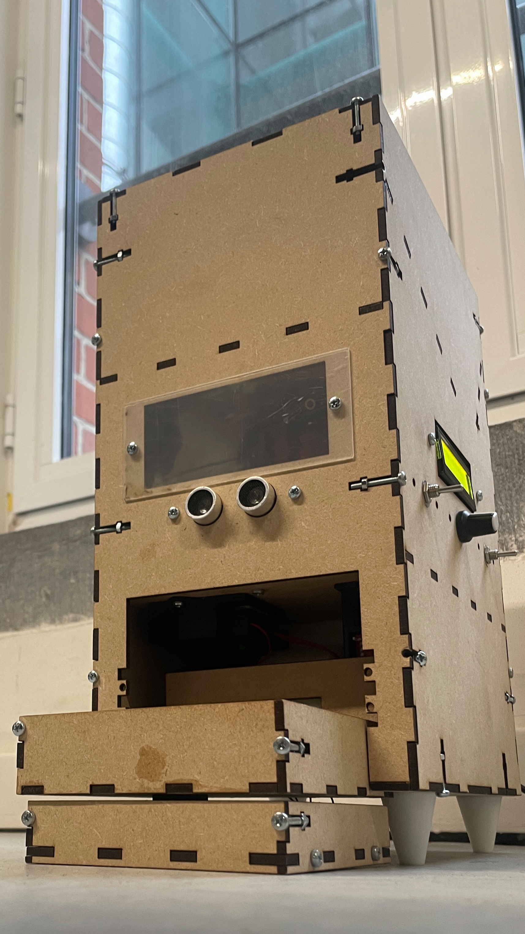
This report describes the design and construction of the prototype of a “Cat Automatic Feeder and Entertainer” carried out in Design Methodology and Mechatronics 1 subjects at VUB as part of the Bruface master of mechantronics at VUB and ULB universities. The idea is simple: building a device that can take care of a cat during a long weekend, taking care of their nutrition and mental health. It will be able to feed the pet the appropriate amount of food at feeding times. In addition, whenever necessary, it will provide an entertaining game to clear the cat's mind. The origin of this idea stems from the lack of a complete product in the market and the need for cat owners to be unconcerned about their cats for a few days.
The design will consider every possible constraint to achieve all the objectives, such as safety and correct feeding. The building has been developed by laser-cutting for simple and flat parts pieces and 3D printing for more complex ones. The whole design has been carefully designed to consider the space requirements of all components. The materials have been chosen to achieve ecological and functional requirements.
The electronics and programming subsystems have been implemented in an Arduino Uno, using different modules to take every signal and control the actuators when necessary. Every sensor and motor has been deeply researched to understand the required power supply and code to define the inputs and outputs.
Every subsystem has been tested before being implemented into the general system. In this way, unique errors can be detected and solved.
| Qty | Value | Footprint | References |
|---|---|---|---|
| 4 | Conn_01x03_Pin | Connector_PinHeader_2.54mm:PinHeader_1x03_P2.54mm_Vertical | J3, J4, J5, J12 |
| 3 | Conn_01x02_Pin | TerminalBlock:TerminalBlock_bornier-2_P5.08mm | J7, J8, J10 |
| 2 | Conn_01x04_Pin | Connector_PinHeader_2.54mm:PinHeader_1x04_P2.54mm_Vertical | J2, J6 |
| 1 | Arduino_UNO_R3 | Module:Arduino_UNO_R3 | A1 |
| 1 | Conn_01x04_Socket | Connector_PinHeader_2.54mm:PinHeader_1x04_P2.54mm_Vertical | J9 |
| 1 | Conn_01x04_Socket | Connector_JST:JST_EH_B4B-EH-A_1x04_P2.50mm_Vertical | J1 |
| 1 | Conn_01x09_Pin | Connector_PinHeader_2.54mm:PinHeader_1x09_P2.54mm_Vertical | J11 |
AndersBNielsen/Relatively-Universal-ROM-Programmer
Hardware to program W27C512 EEPROM or any 24/28/32 pin ROM requiring from 5V to 27V programming voltage.

AlanFord/self-balancing-stick
Dual Axis Reaction Wheel Inverted Pendulum

Edging-Machines/Edging-Machines
This repository is intended to contain as much information as possible about building, designing, prototyping, and using automated edging machines.

PedroCNeves/AC_ChargingStation
A learning project to create an EV AC Charging station based on an Arduino Uno

jonsag/arduTester
An arduino component tester based on https://create.arduino.cc/projecthub/plouc68000/ardutester-v1-13-the-arduino-uno-transistor-tester-dbafb4


ICRS/101
The all-new open source Robotics 101 course from ICRS. It's specifically designed to be run in hackspaces, after school clubs and university societies.

It measures 53.6 × 68.9 mm and has 2 copper layers, 1.6 mm thick.
13 parts, built around the ARDUINO UNO R3. The full list of its parts is on this page, with links to each part's symbol and footprint where PCBKit's library has them.
From the MohamedRadwan180/Automatic-Pet-Feeder repository on GitHub, at the commit this page was made from: the board is Arduino Shield PCB/PCB Design Files - Kicad/MECHX-Pet Feeder.kicad_pcb and its schematic Arduino Shield PCB/PCB Design Files - Kicad/MECHX-Pet Feeder.kicad_sch. PCBKit opens the board in the browser, with nothing to install.
Its repository publishes it under the MIT licence: you may reuse it on that licence's terms (keep the author's notice, and for a copyleft licence share your changes alike).