

2 layers137.2 × 83.8 mm
GeneralPurposeAlarmDevicePCB
PubInv/general-purpose-alarm-device
A general purpose alarm device (with software) as a module for medical devices (and others)
140 parts7AGPL-3.0

 mlh5599/FanPWMtoRotorLock
Converts the output from a 12v PWM fan to a rotor lock detector signal
FanPWMtoRotorLock is an open-source printed circuit board by mlh5599, from the mlh5599/FanPWMtoRotorLock repository on GitHub, published under the MIT licence. It is a 2-layer board of 21 × 9 mm with 13 parts on 10 nets, routed with 115 tracks and 6 vias.
It is built around the NE555P and MMBT2907ALT1G. Its parts include 6 resistors, 2 capacitors, 2 transistors, 2 connectors and 1 IC.
Utilizes a missing pulse detector based on the circuitry here to convert the output from a 12v PWM fan to a rotor lock detector signal.
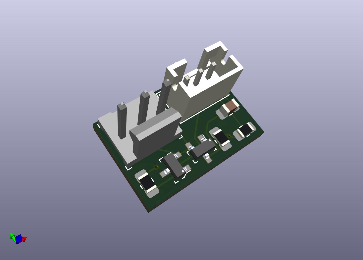
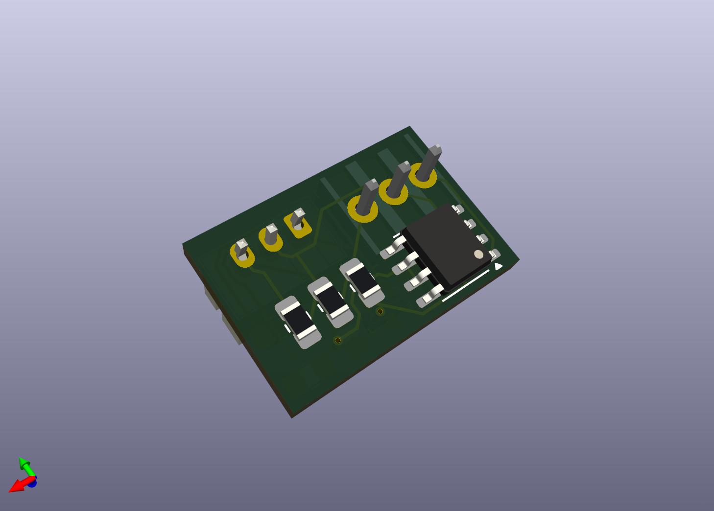
| Qty | Value | Footprint | References |
|---|---|---|---|
| 5 | 10K | Resistor_SMD:R_0805_2012Metric_Pad1.20x1.40mm_HandSolder | R1, R2, R3, R5, R6 |
| 1 | .1uf | Capacitor_SMD:C_0805_2012Metric_Pad1.18x1.45mm_HandSolder | C2 |
| 1 | 0022232031 | Connector_JST:JST_PH_B3B-PH-K_1x03_P2.00mm_Vertical | J2 |
| 1 | 0022232031 | digikey-footprints:PinHeader_1x3_P2.54mm_Drill1.02mm | J1 |
| 1 | 100 | Resistor_SMD:R_0805_2012Metric_Pad1.20x1.40mm_HandSolder | R4 |
| 1 | 10uf | Capacitor_SMD:C_0805_2012Metric_Pad1.18x1.45mm_HandSolder | C1 |
| 1 | MMBT2222A-7-F | digikey-footprints:SOT-23-3 | Q2 |
| 1 | MMBT2907ALT1G | digikey-footprints:SOT-23-3 | Q3 |
| 1 | NE555P | Package_SO:SOIC-8_3.9x4.9mm_P1.27mm | U1 |
PubInv/general-purpose-alarm-device
A general purpose alarm device (with software) as a module for medical devices (and others)

Konkzor/LinKey
Une clé WIFI lisant la sortie TIC du Linky connectée au broker MQTT d'un Home Assistant


Fish-in-a-Barrel/Nixie
This is my Nixie clock project. It was created as an excuse to learn more about electronics and it touches on power circuits, microcontrollers, serial communications, and more.


baldengineer/bit-preserve
Project for capturing vintage, classic, aka old computer schematics in KiCad.

The-Invent0r/8-bit-Computer-PCB
These are the KiCAD files for my 8-Bit Computer.

DarcyJProjects/touchtone555
An open-source DIY, NE555-based analogue synthesizer - play notes with a stylus
It measures 21 × 9 mm and has 2 copper layers, 1.6 mm thick.
13 parts, built around the NE555P and MMBT2907ALT1G. The full list of its parts is on this page, with links to each part's symbol and footprint where PCBKit's library has them.
From the mlh5599/FanPWMtoRotorLock repository on GitHub, at the commit this page was made from: the board is FanPWMtoRotorLock.kicad_pcb and its schematic FanPWMtoRotorLock.kicad_sch. PCBKit opens the board in the browser, with nothing to install.
Its repository publishes it under the MIT licence: you may reuse it on that licence's terms (keep the author's notice, and for a copyleft licence share your changes alike).