2 layers100 × 100 mm
Mist1010
UzixLS/mist1010-board
10x10cm PCB variant of MIST FPGA project for G738/G706 enclosure
273 parts43MIT

 mlainez/midiboard
A small MIDI interface board: opto-isolated MIDI IN, buffered MIDI OUT, optional hard THRU, a 3V3/5V slide switch, and on-board footprints for two right-angle DIN-5 jacks.
Midiboard is an open-source printed circuit board by mlainez, from the mlainez/midiboard repository on GitHub, published under the CC-BY-SA-4.0 licence. It is a 2-layer board of 46 × 39 mm with 20 parts on 21 nets, routed with 150 tracks and 3 vias.
It is built around the 74LVC1G17Z, H11L1SM and CC0603KRX7R9BB104, with the 1N4148W among its other parts. Its parts include 7 resistors, 4 connectors, 2 capacitors, 2 ICs and 1 diode.


A small MIDI interface board: opto-isolated MIDI IN, buffered MIDI OUT, optional hard THRU, a 3V3/5V slide switch, and on-board footprints for two right-angle DIN-5 jacks.
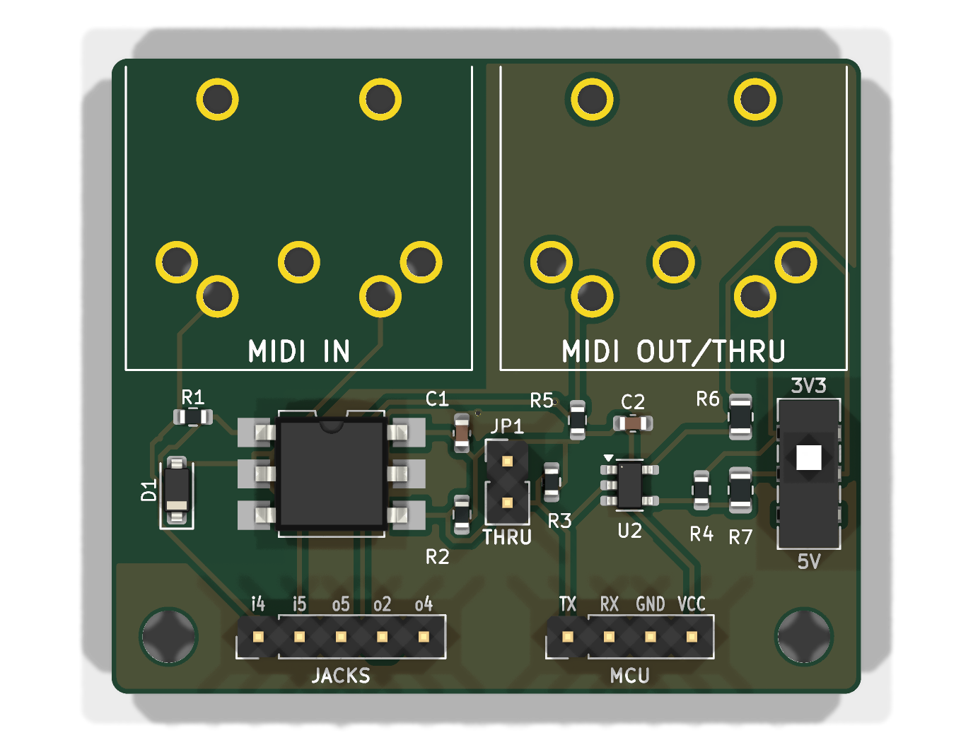
Board: 46 x 39 mm, 2 layers, all SMD parts on top, 2x M3 mounting holes.
Everything to upload is in jlcpcb/:
| File | Where |
|---|---|
midiboard-gerbers.zip | PCB order: "Add gerber file" |
midiboard-BOM.csv | PCB Assembly step: BOM |
midiboard-CPL.csv | PCB Assembly step: CPL / pick & place |
Upload the gerber zip. Defaults are fine (2 layers, 1.6 mm, any colour/finish). For "Mark on PCB" choose Remove Mark (there is no order-number placeholder on the board).
Enable PCB Assembly, Economic, Top side.
Upload BOM and CPL. All 13 placed parts should match automatically:
| Ref | Value | Package | LCSC | Type |
|---|---|---|---|---|
| U1 | H11L1SM optocoupler (onsemi) | SMD DIP-6 | C899473 | extended |
| U2 | 74LVC1G17W5-7 Schmitt buffer | SOT-23-5 | C151394 | extended |
| D1 | 1N4148W | SOD-123 | C81598 | basic |
| SW1 | C&K JS202011JCQN DPDT slide switch | SMD | C221665 | extended |
| R1, R4, R5 | 220 R | 0603 | C22962 | basic |
| R2 | 470 R | 0603 | C23179 | basic |
| R3 | 10 k | 0603 | C25804 | basic |
| R6 | 33 R | 0805 | C17634 | basic |
| R7 | 10 R | 0805 | C17415 | basic |
| C1, C2 | 100 nF X7R | 0603 | C14663 | basic |
In the placement preview, check the pin-1 dots: U1 pin 1 is top-left (towards R1/D1), U2 pin 1 is top-left (silkscreen triangle). The CPL already applies the KiCad-to-JLCPCB rotation offsets (-90 deg for SOT-23-5 and SMD DIP-6).
| Ref | Part | Note |
|---|---|---|
| J1, J2 | DIN-5 female, right angle, PCB mount: Legion/Haoyu DIN-504, LCSC C23689428 | Any CUI SDS-50J-footprint jack fits |
| J3 | 1x4 pin header 2.54 mm | MCU side |
| J4 | 1x5 pin header 2.54 mm | Only if you use panel-mount jacks instead of J1/J2 |
| JP1 | 1x2 pin header 2.54 mm + jumper cap | HARD THRU selector |
The DIN jacks can also be added to the JLCPCB order as through-hole assembly if you prefer.
J3 - MCU (3.3 V or 5 V logic, set SW1 to match)
| Pin | Name | Connect to |
|---|---|---|
| 1 | TX | MCU UART TX (31250 baud) |
| 2 | RX | MCU UART RX |
| 3 | GND | GND |
| 4 | VCC | 3.3 V or 5 V supply, same as the MCU logic level |
J4 - panel jacks: i4/i5 to MIDI IN pins 4/5, o5/o2/o4 to MIDI OUT pins 5/2/4.
These are wired in parallel with the on-board J1/J2 footprints.
SW1 3V3 / 5V: slide towards the jacks (3V3) for a 3.3 V MCU, towards the headers (5V) for a 5 V MCU.
It only sets the MIDI OUT drive; RX simply swings to VCC. A wrong setting is not harmful: 5 V on the 3V3
setting pushes ~15 mA into the receiver, 3.3 V on the 5V setting gives ~3 mA, which some receivers may not
detect.
JP1 HARD THRU (2-pin header, open by default): fit a 2.54 mm jumper cap to echo MIDI IN straight to the OUT jack. When bridged, leave J3 TX unconnected.
build.sh runs all of these and stops on failure:
scripts/check_netlist.py: the schematic netlist matches scripts/design.py.scripts/check_gerbers.py: rasterizes the copper gerbers, joins layers through the drill file's plated
holes, and derives connectivity from copper alone, then compares it with design.py (opens, shorts and
NC pads). Mutating the expected design makes it fail, so it does detect wiring errors.Checked by hand against datasheets: H11L1 pinout and inverting output (onsemi), 74LVC1G17 SOT25 pinout (Diodes Inc), JS202011 contact positions (C&K: slider towards pin 1 closes 1-2 and 4-5), DIN-504 PCB layout (Legion and Haoyu drawings agree), and the JLCPCB/EasyEDA footprints of C899473, C151394, C81598 and C221665 for the CPL rotations and diode polarity.
midiboard.kicad_dru lets through-hole pads have a single thermal spoke per layer: they are plated through
both ground pours, so the connection is solid either way.
KiCad project: midiboard.kicad_pro / .kicad_sch / .kicad_pcb, project footprint in lib/midiboard.pretty.
jlcpcb/midiboard-schematic.pdf is a printable schematic.
Everything is generated from scripts/design.py (parts, LCSC numbers, nets):
FREEROUTING_JAR=/path/to/freerouting-2.1.0.jar ./build.shbuild.sh generates the schematic, runs ERC, checks the schematic netlist against design.py, places the
board, autoroutes it with Freerouting (headless), adds the ground pours, runs DRC with schematic parity and
writes the JLCPCB files, then checks the gerber copper. It needs KiCad 7 pcbnew Python, kiutils, numpy,
scipy, pillow, gerbv, Java 21 and a KiCad >= 8 kicad-cli (defaults to the KiCad Flatpak).
Copyright (c) 2026 Marc Lainez. Licensed under
Creative Commons Attribution-ShareAlike 4.0 International
(CC BY-SA 4.0), see LICENSE.
| Qty | Value | Footprint | References |
|---|---|---|---|
| 3 | 220 | Resistor_SMD:R_0603_1608Metric | R1, R4, R5 |
| 2 | 100nF | Capacitor_SMD:C_0603_1608Metric | C1, C2 |
| 2 | M3 | MountingHole:MountingHole_3.2mm_M3 | H1, H2 |
| 1 | 10 | Resistor_SMD:R_0805_2012Metric | R7 |
| 1 | 10k | Resistor_SMD:R_0603_1608Metric | R3 |
| 1 | 1N4148W | Diode_SMD:D_SOD-123 | D1 |
| 1 | 33 | Resistor_SMD:R_0805_2012Metric | R6 |
| 1 | 3V3/5V | Button_Switch_SMD:SW_DPDT_CK_JS202011JCQN | SW1 |
| 1 | 470 | Resistor_SMD:R_0603_1608Metric | R2 |
| 1 | 74LVC1G17 | Package_TO_SOT_SMD:SOT-23-5 | U2 |
| 1 | H11L1SM | Package_DIP:SMDIP-6_W9.53mm | U1 |
| 1 | HARD THRU | Connector_PinHeader_2.54mm:PinHeader_1x02_P2.54mm_Vertical | JP1 |
| 1 | JACKS | Connector_PinHeader_2.54mm:PinHeader_1x05_P2.54mm_Vertical | J4 |
| 1 | MCU | Connector_PinHeader_2.54mm:PinHeader_1x04_P2.54mm_Vertical | J3 |
| 1 | MIDI IN | midiboard:DIN-5_Female_Horizontal_DIN-504 | J1 |
| 1 | MIDI OUT/THRU | midiboard:DIN-5_Female_Horizontal_DIN-504 | J2 |
It measures 46 × 39 mm and has 2 copper layers, 1.6 mm thick.
20 parts, built around the 74LVC1G17Z, H11L1SM, CC0603KRX7R9BB104 and 1N4148W. The full list of its parts is on this page, with links to each part's symbol and footprint where PCBKit's library has them.
From the mlainez/midiboard repository on GitHub, at the commit this page was made from: the board is midiboard.kicad_pcb and its schematic midiboard.kicad_sch. PCBKit opens the board in the browser, with nothing to install.
Its repository publishes it under the CC-BY-SA-4.0 licence: you may reuse it on that licence's terms (keep the author's notice, and for a copyleft licence share your changes alike).
UzixLS/mist1010-board
10x10cm PCB variant of MIST FPGA project for G738/G706 enclosure

wero1414/fm1-midi-dongle.
A small stick that plugs into the M-VAVE FM-1's USB-C port and gives it a TRS MIDI OUT and an isolated TRS MIDI IN.

MF-Room/mseq_pcb
KiCad 10 hardware design for MSeq embedded, the microcontroller implementation of the MSeq MIDI sequencer.

frc971/electrical
This repo contains the electrical files for the 971 FRC team. The files include PCBs and the electrical system diagrams. The PCBs are created using KiCad.

kfilipekk/iridium_drone
STM32H743 flight controller that navigates without GPS from Iridium satellite Doppler

Alexpoopy1/Claude-Micro
A 13-key agent macropad on clear MX switches: six frosted status keys, seven command keys, a rotary reasoning dial, a planar joystick, a five-pad capacitive touch strip and a 19-LED RGB chain.

