2 layers100 × 50 mm

 mlab-modules/RFIQINT011
UTP cable RF signal I/Q interface for QFHMIX module with punch-down blocks
RFIQINT01B is an open-source printed circuit board by mlab-modules, from the mlab-modules/RFIQINT01 repository on GitHub, published under the GPL-3.0 licence. It is a 2-layer board of 60.5 × 50.3 mm with 48 parts on 32 nets, routed with 614 tracks and 126 vias.
It is built around the MAX9321EKA, LM1117-3.3 and BLM21PG331SN1D. Its parts include 17 capacitors, 14 resistors, 6 connectors, 3 ICs and 1 diode.


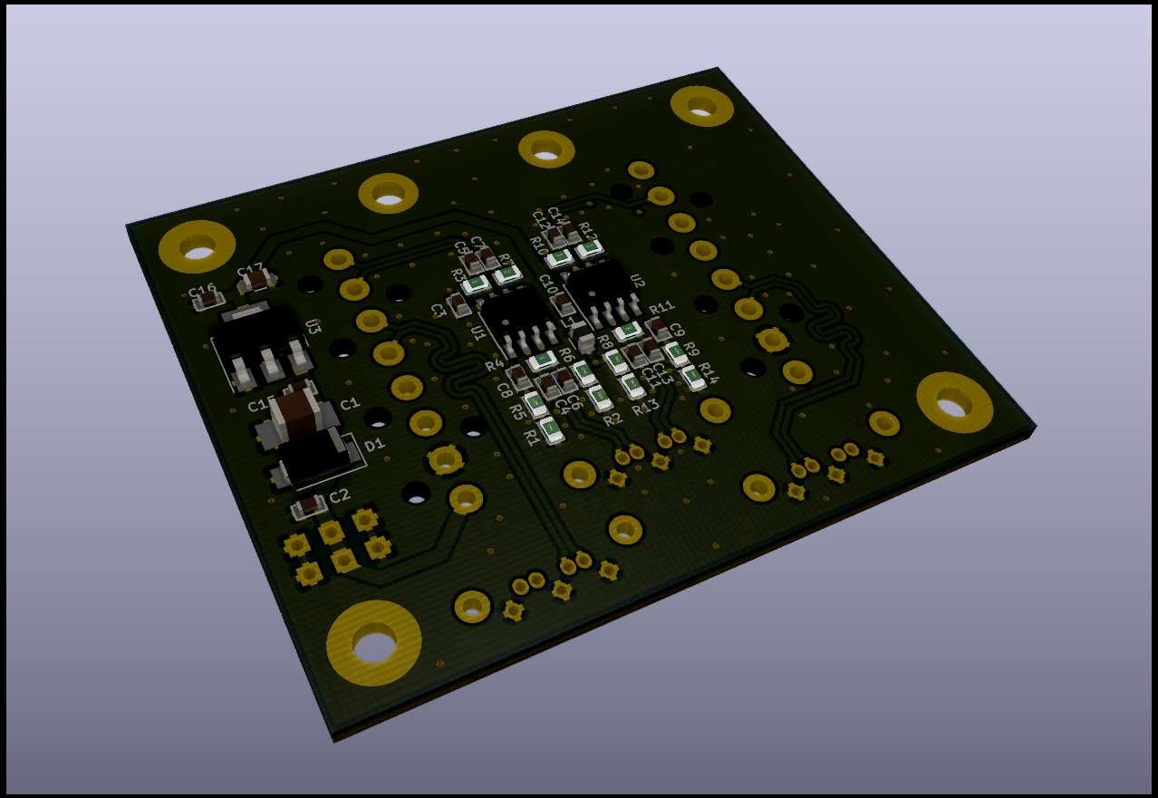
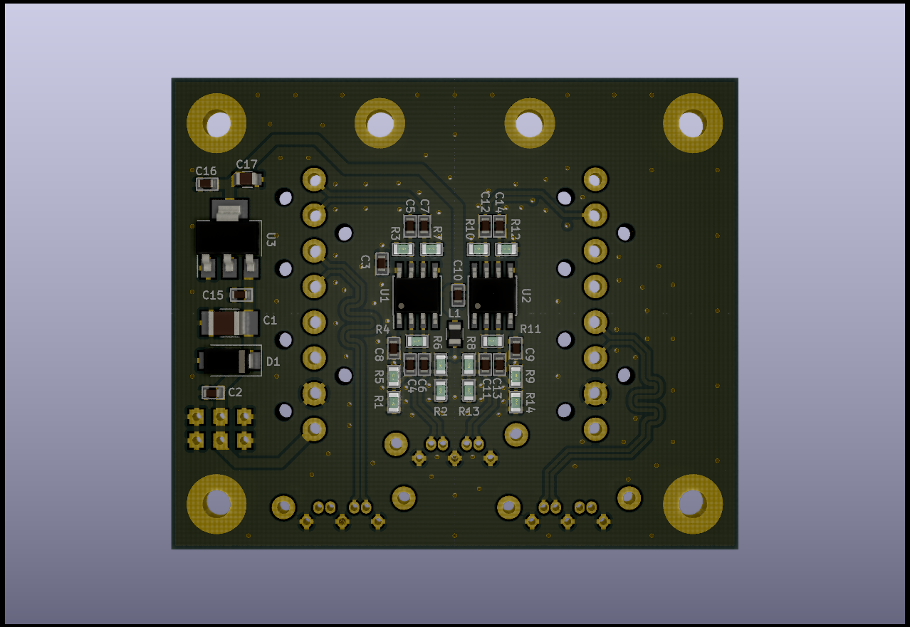
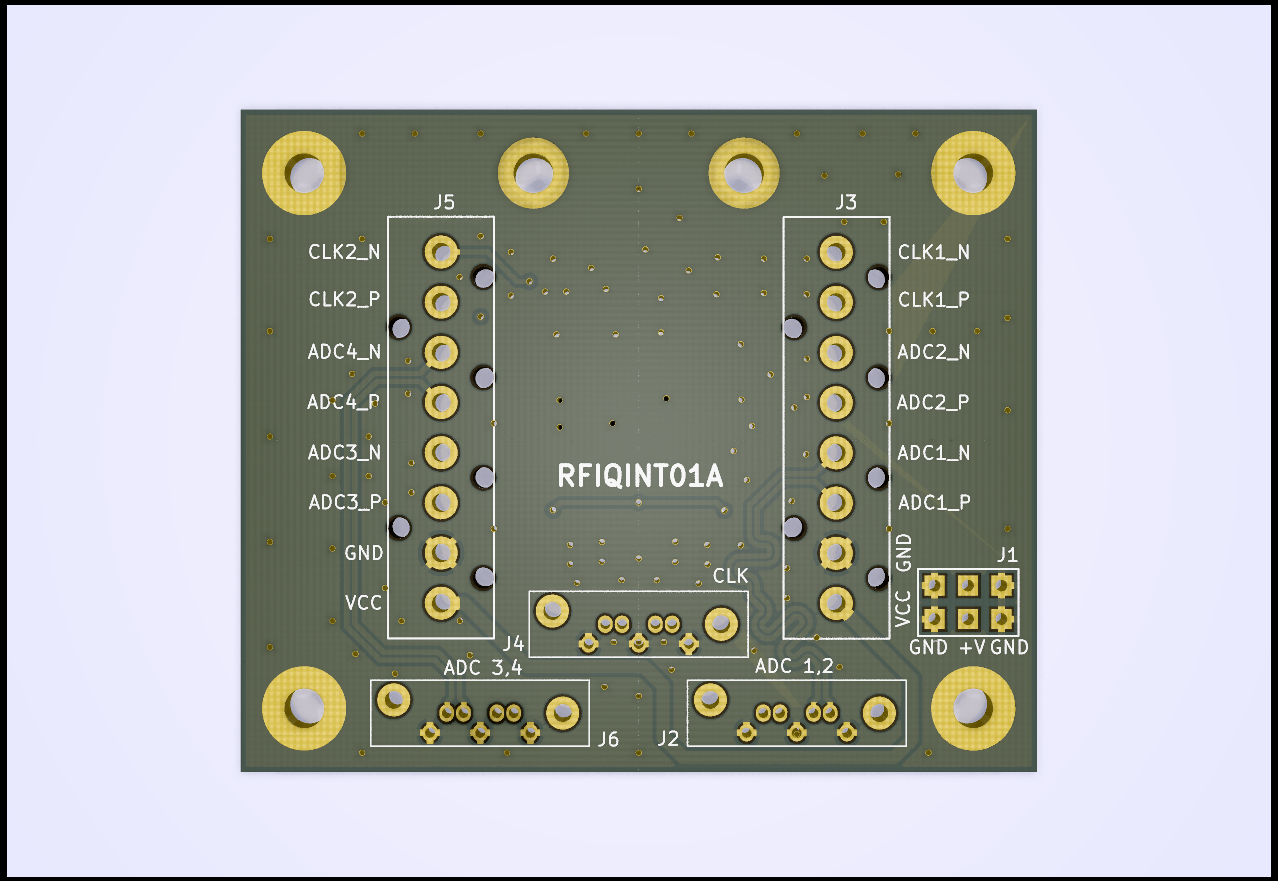
| Parameter | Value | Description |
|---|---|---|
| Frequency range | 100 - 1000 MHz | |
| Interface | RJ45 | CAT 7/A cable is expected |
| Operating and storage temperature | -20 - +30°C | |
| Operational input voltage for Antenna | 9 - 12 V | |
| Operational input voltage | 3.3-3.6 V | 130 mA for LO buffer core |
| Qty | Value | Footprint | References |
|---|---|---|---|
| 15 | 100nF | Capacitor_SMD:C_0603_1608Metric | C2, C3, C4, C5, C6, C7, C8, C9, C10, C11, C12, C13, C14, C15, C16 |
| 8 | 130 | Resistor_SMD:R_0603_1608Metric | R3, R5, R6, R7, R8, R9, R10, R12 |
| 6 | HOLE | Mlab_Mechanical:MountingHole_3mm | M1, M2, M3, M4, M5, M6 |
| 4 | 82 | Resistor_SMD:R_0603_1608Metric | R1, R2, R13, R14 |
| 3 | SATA7-67491-1030 | Mlab_CON:SATA-7_THT_VERT_2 | J2, J4, J6 |
| 2 | 100 | Resistor_SMD:R_0603_1608Metric | R4, R11 |
| 2 | 10uF/16V | Capacitor_SMD:C_0805_2012Metric | C1, C17 |
| 2 | HEADER_1x08 | Mlab_CON:IDC381-8-110 | J3, J5 |
| 2 | MAX9321 | Package_SO:SOIC-8_3.9x4.9mm_P1.27mm | U1, U2 |
| 1 | BLM21PG331SN1D | Inductors_SMD:L_0805 | L1 |
| 1 | HEADER_2x04_PARALLEL | Mlab_Pin_Headers:Straight_2x04 | J1 |
| 1 | LM1117-3.3 | Package_TO_SOT_SMD:SOT-223-3_TabPin2 | U3 |
| 1 | M4 | Diode_SMD:D_SMA | D1 |
It measures 60.5 × 50.3 mm and has 2 copper layers, 1.6 mm thick.
48 parts, built around the MAX9321EKA, LM1117-3.3 and BLM21PG331SN1D. The full list of its parts is on this page, with links to each part's symbol and footprint where PCBKit's library has them.
From the mlab-modules/RFIQINT01 repository on GitHub, at the commit this page was made from: the board is hw/sch_pcb/RFIQINT01B.kicad_pcb and its schematic hw/sch_pcb/RFIQINT01B.kicad_sch. PCBKit opens the board in the browser, with nothing to install.
Its repository publishes it under the GPL-3.0 licence: you may reuse it on that licence's terms (keep the author's notice, and for a copyleft licence share your changes alike).


oresat/oresat-c3-hardware
C3 (Command, Communication, and Control) our Command and Data Handling (C&DH) card.

freeDSP/freeDSPx-ADAT-IO-x4
The freeDSPx ADAT IO x4 is a digital IO expansion board for the freeDSP family. It provides 4 Lightpipe(I2S) inputs and 4 Lightpipe outputs via single Toslink Cable.

CyberPit/FreeDSP_Classic_SMD_AB_plus-II
An extended version of FreeDSP Classic SMD A/B


