DIGITAL ELECTRONICS 1
2021, Faculty of Electrical Engineering and Communication FEKT

Title: Project 2021
Topic: 3. Console for bike with hall sensor, measuring and displaying speed, traveled distance and burnt calories
Time Window:
- Start of Project: April 7
- End of Project: May 4
Supervisor: doc. Ing. Tomáš Frýza, Ph.D.
Vivado Teachers: doc. Ing. Tomáš Frýza, Ph.D., Ing. Stanislav Rozum
3. Console for bike with hall sensor, measuring and displaying speed, traveled distance and burnt calories
Team members
- Martin Kousal, ID= 221063
Link to GitHub project folder
- Matej Ledvina, ID= 221339
Link to GitHub
- Tomáš Kříčka, ID= 223283
Link to GitHub
- Samuel Košík, ID= 221056
Link to GitHub
Project objectives
Our application uses two hall sensors for measuring speed, traveled distance, burnt calories and time (not by the hall sensor).
This data is shown on four 7segment displays (one part).
- Calories counting
- Total time
- Total distance traveled
- Trip distance traveled
- Speed measuring
Modes can be selected by pressing buttons (see below).
One hall sensor is used for measuring speed and traveled distance. Another one is for calories counting.
Burnt calories will increase only by stepping the pedals, not by downhill riding!
Hardware description
Programming Board
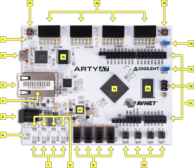
- Main programming board is Arty A7-100T. It has four Pmod connectors (16.), we have used all of them
- Other buttons and LEDs are not used => See Main Board
Main Board
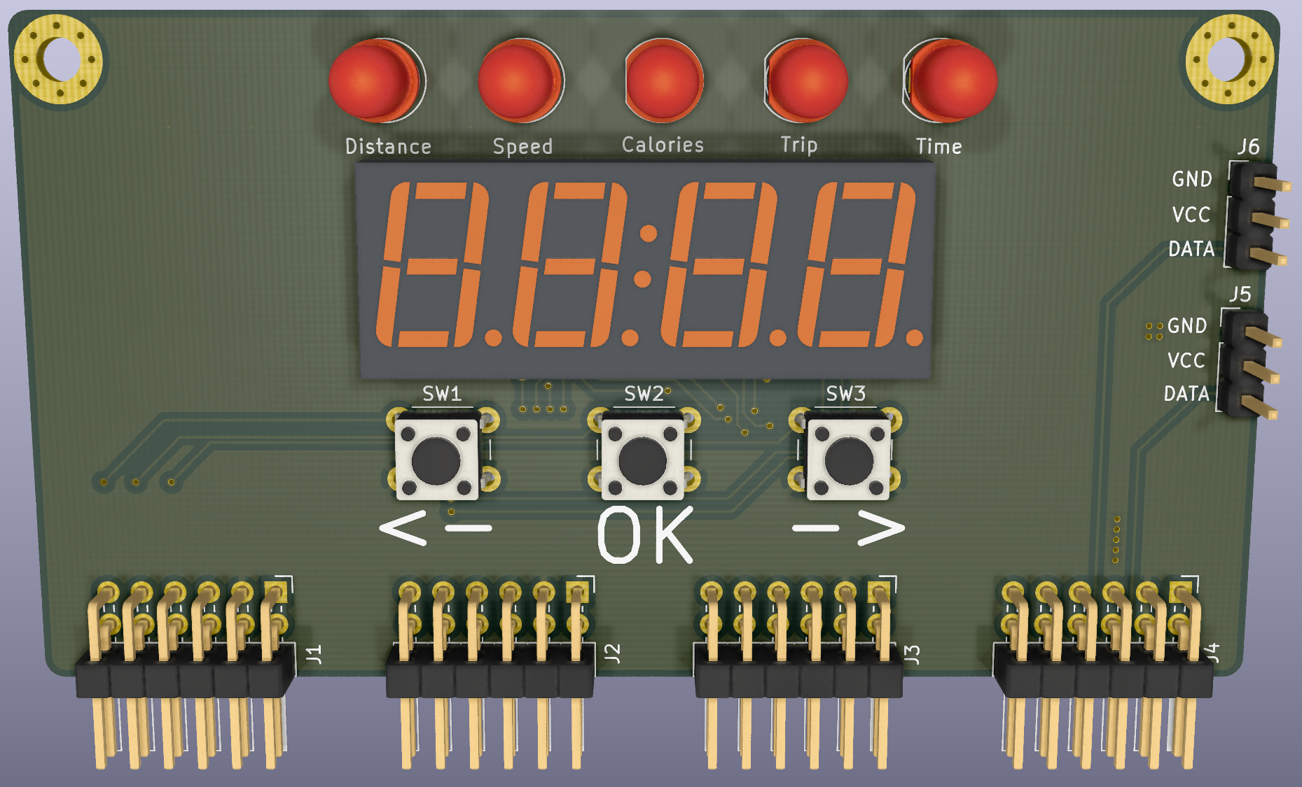
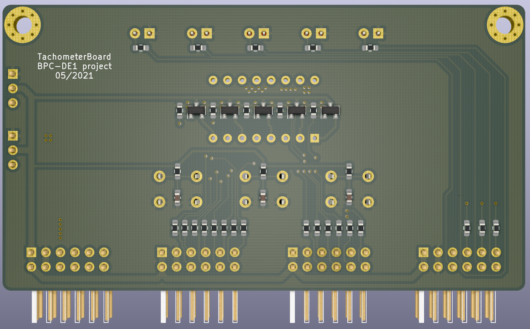
- Schematic
- Consists of: three buttons, 7segment display, Pmod connectors, LED status and two connectors for Hall sensors
- Board is made for direct connection to Arty A7 board. Three buttons are used to controlling the tachometer. LED at the top shows what value is now displayed at the display
- Used seven segment display with middle double dot and dots for decimal is TDCG1050m - datasheet
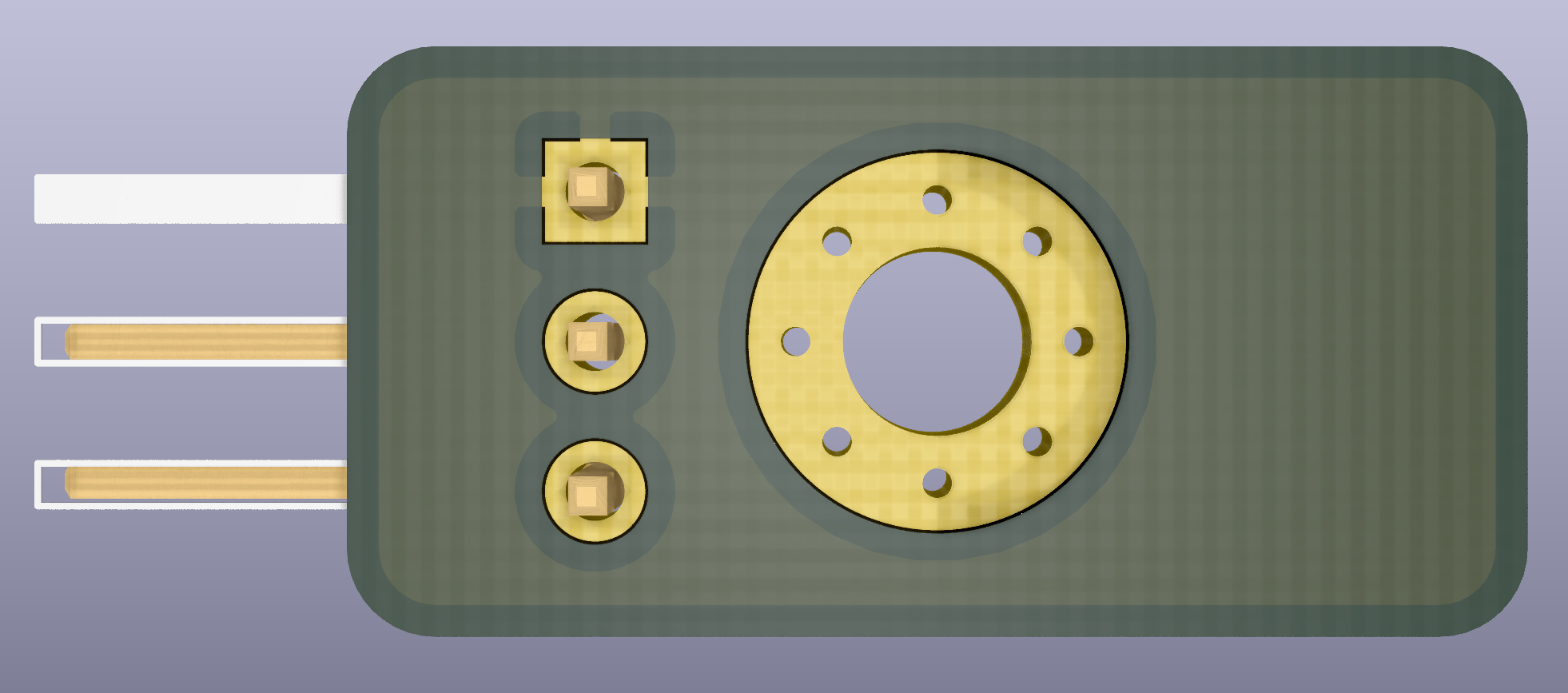
Hall sensor board
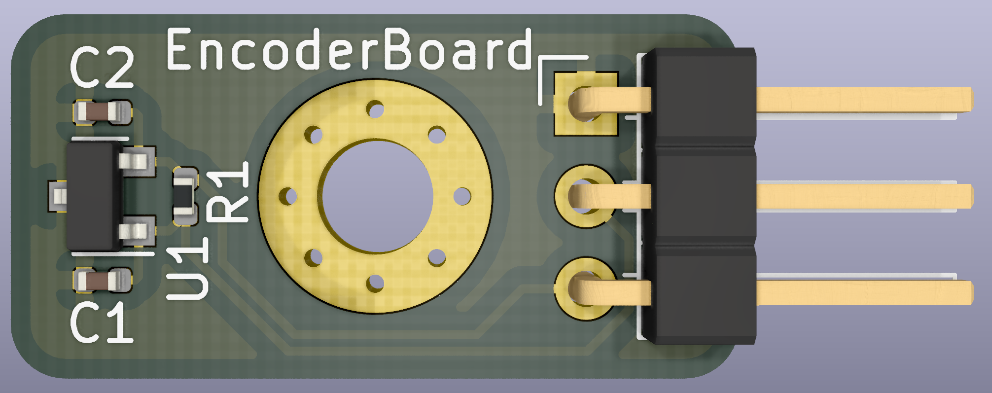
- Schematic
- Hall sensor board only consists of hall sensor and a few passive components that are described in datasheet and connector
- You can screw it by using M3 screw to your bicycle
- Used sensor is MH253 - datasheet
VHDL modules description
Buttons
Button_int:
- This block reads the input from real world buttons and translates them to commands which will be sent to the state_machine controller. When buttons up or down are pressed, the interface will enter a cooldown state when no additional button presses will be registered (to prevent jitter) after the cooldown passes, the interface will send an up or down command out
- If the ok button is pressed, the device enters the cooldown state, after which it will wait for a longer ammount of time. If no additional ok button press is registered, the interface will send out an startstop command
- If, however, the ok button would be pressed again, the interface will send out the reset command
Traveled distance
km_total:
- This block counts the travel distance and sends it out to the display. Every 100 m (meters) an pulse will appear on the
meters_i which will add to the total count of up to 999,9 km
- When the trip mode is activated the block will count the trip time and send it to the display instead, the total time is being still counted in the background
- rst signal will make the current displayed data reset to 0
- The enable signal will be present if the trip is not paused, on pause the trip data is not counted
- This block automaticaly wipes previous trip data when the mode is turned on
This block also contains a function which converts the traveled distance from binary integer to BCD code to be displayed on the 4 digit 7 segment display.
Main controling module
state_machine:
- This is the main utility block of the device. It recives commands from the button interface and switches the outputs accordingly. Inputs
up_i and down_i will cycle through the 4 modes of the device and light up their status LED
- While in a mode the data stream from its block will be sent to be displayed on the segment display via the
data_o, with added decimal point or double dot if needed
- While in a mode the reset and ok commands also aply for the selected block only. The trip mode is special, because it does not generate data on its own, when activated, it will send a mode change command to all blocks which will now store and display data in an additional variable as well as keeping the total count going
- The status LED of trip will remain on as we cycle through the other modes until it is paused by the startstop button or turned off via the reset. At this point all trip data will be reset from all blocks and the normal total data will be displayed
Time mode
total_time:
- This block acts as a stopwatch. When startstop is applied, it will start or pause the counting
- Reset will reset the total time
- When the trip mode is enabled, the stopwatch will automatically start counting the trip time and will reset before every trip is started
This block also contains a function which converts the total time from binary integer to BCD code to be displayed on the 4 digit 7 segment display.
SENSOR
sensor:
- This block is used to calculate actual speed and triggering pulse every 100 meters for counting travelled distance
- Uses input from hall sensor mounted at the front wheel. Output one trigger signal every counted 100 meters and calculate actual real speed and set it to display output
7 Segment Driver Module
- This block consists of 4 smaller modules:
CLOCKUP_DOWN_COUNTERDRIVER_4X7SEGDECODER_7SEG
CLOCK:
- Generates 100MHz clock
- This periodic signal is used in module
UP_DOWN_COUNTER, which reacts on rising edge of the signal
- Originally uses 4ms for each segment
UP_DOWN_COUNTER:
- According settings (g_CNT_WIDTH), counts as the edge of the clock signal rises
DRIVER_4X7SEG:
- Main module, drives four 7segment displays. It is determinated by
CLOCK and UP_DOWN_COUNTER
- Process MUX uses above modules to set data_outputs to each 7segment display
- Input is a 16bit unsigned (
b"xxxx xxxx xxxx xxxx")
DECODER_7SEG:
This module is used for displaying data on 7segment display. If have more displays, MUX has to be used
Both, common cathode and common anode can be used as well
Calories Mode
calories:
- This block calculates burned calories by measuring the time between each pedals rotations
- Rotation is captured by hall probe attached to pedal
- The 100 MHz clock is used for counting time. Every 0.5s a number is increased, which recalculates the calories formula
- When signal from hall probe is not generating for 2s, the number that was increasing is stopped. The amount of burned calories is sent to display
Testbenches and simulations
Button_int:
- Shows states of
button_int block
- In order to save time and make the inner working of this device more clear, all simulated data has been sped up

km_total:
- Screenshot demos how the counting works
- In order to save time and make the inner working of this device more clear, all simulated data has been sped up

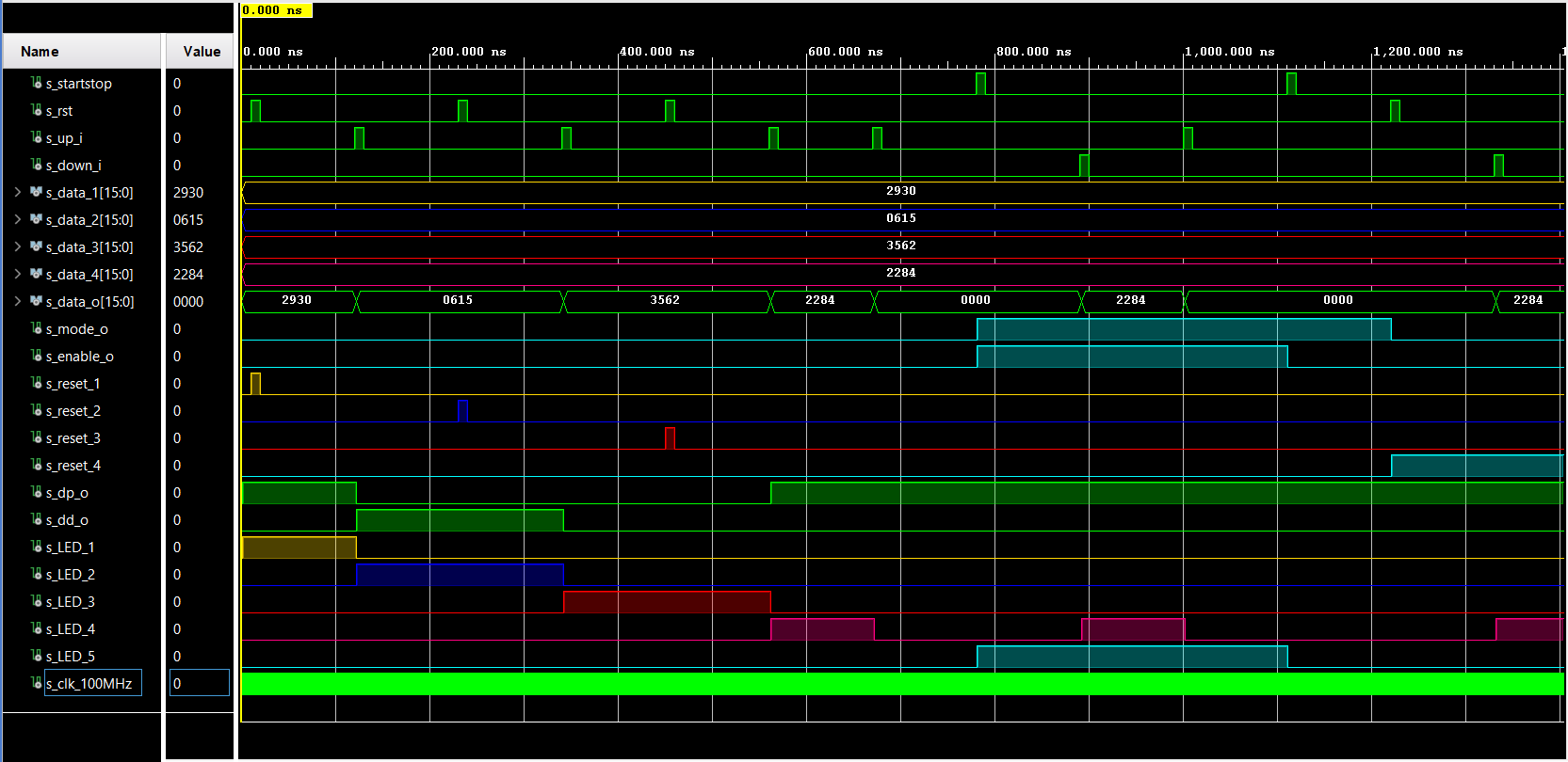
state_machine:
- Screenshot below represents testbench of main unit
- In order to save time and make the inner working of this device more clear, all simulated data has been sped up
total_time:
- Funcionality of total time counting is shown by this signals
- In order to save time and make the inner working of this device more clear, all simulated data has been sped up

sensor:
- First waveform shows how the speed calculation works. Calculated speed is written to the
s_disp_o, which is 16bit word and is here until the new value is calculated

- Second waveform shows pulsing at the
s_trigger_o every 50 sensor's tick, which is equal to the 100 meters in real distance

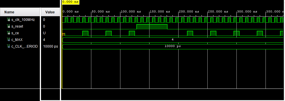
CLOCK:
- Generates 100 MHz clock signal
UP_DOWN_COUNTER:
- As internal values set, counts with edge of the clock
- 0-31 states:
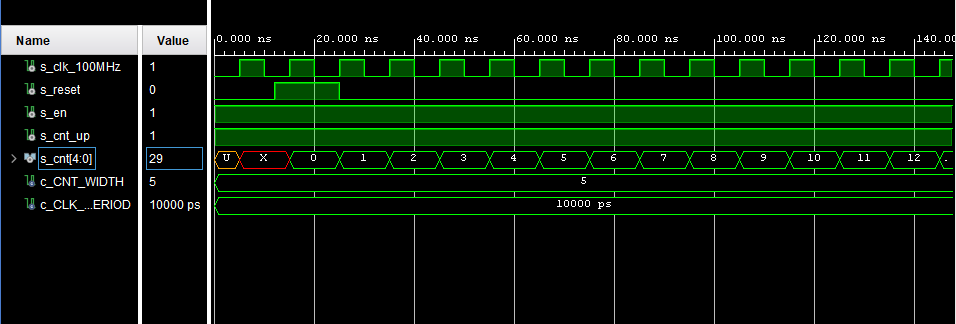
- 0-31 states:
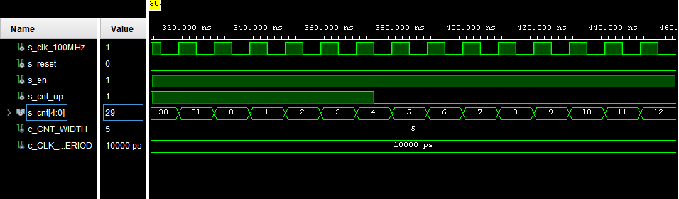
- 0-4 states = This is used in our application
- Four 7segment displays are controlled by this states

DRIVER_4X7SEG:
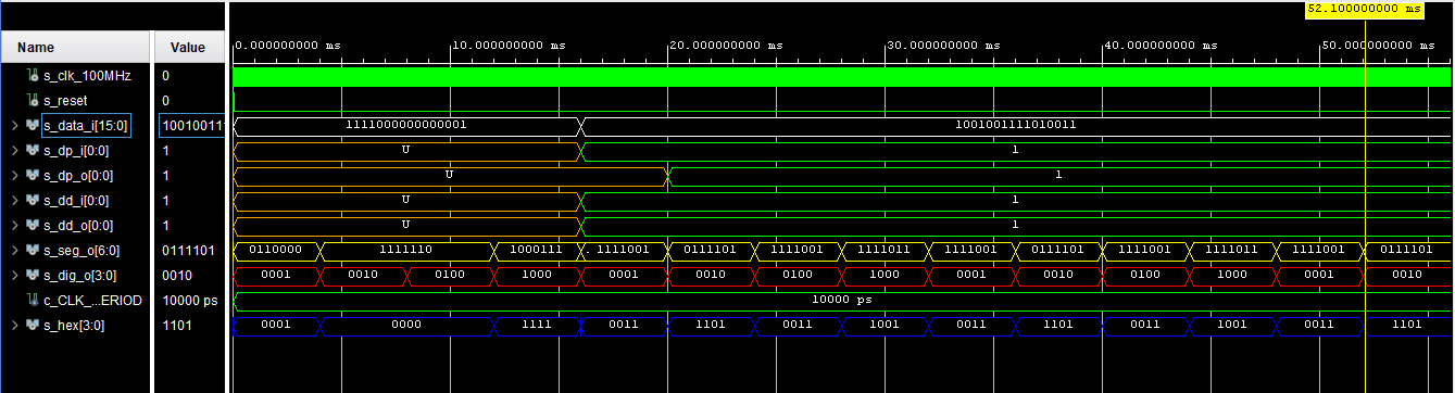
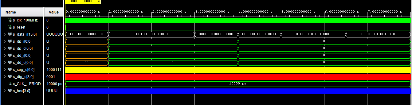
- These screenshots show how the multiplexer works
s_data is the main 16bit data inputs_hex is the 4bit data output, which is used in DECODER_7SEG. This module decodes the 4bit data value and diplays it on a specific 7segment displays_dig_o shows which one of four displays is being used. b"0001" means display on very right sides_seg_o represents common cathode bits
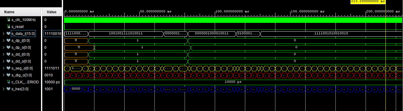
- This screenshot shows a real situation, when input data will be refreshed every one second (tachometer)
- If data is not changed for a while, displays will use last data. This prevents from wrong/unwanted values
DECODER_7SEG:
- Decodes 4bit signal to 7bit (7 segments (+ decimal dot and colon))

calories:
- The simulation is in ratio 1s = 10ms
- In wave form is display calories counting in both modes and amount of burned calories is sending to display
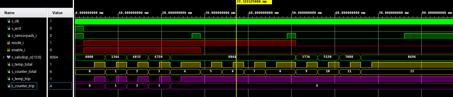
TOP module description and simulations
- TOP module represents the whole project
- Final test schema can be seen below:

- After having main board and hall sensor board done, software can be written into Arty A7 board. Generated bitstream is available here.
Video
Video presentation is available here.
References
Used materials:
- Theoretical knowledge from Digital-Electronics-1 Labs, 2021 > Link
- Labs from classes DE1
- DE1 Lecture PDF > Link
- 7 Segment Display
- Hall sensor
Used programs and its links:
©2021, VUT FEKT, Brno, Czech Republic
Kousal Martin, Ledvina Matej, Kříčka Tomáš, Košík Samuel
For Educational Purposes Only!


