2 layers155 × 140 mm
Control board
Sergio5714/experimental-teg-testbed-firmware
Firmware for STM32 MCU of testbed data acquisition and control system
89 parts2
 mjmorano/Precision-Current-Source
Once it's uploaded connect the Arduino pins to the 6 pin header on the current source as follows:
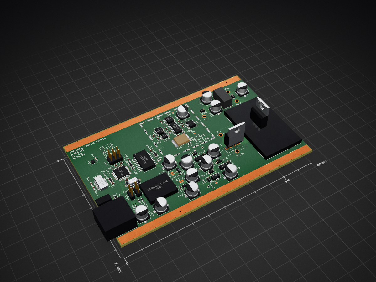
Current Sources Improved is an open-source printed circuit board by mjmorano, from the mjmorano/Precision-Current-Source repository on GitHub. It is a 4-layer board of 120 × 75 mm with 95 parts on 104 nets, routed with 534 tracks and 112 vias.
It is built around the OPA4182ID, PESE1-S5-S24-M and AD7789BRM, with the FT231XS-U, ADR441BR and L78L05CZ among its other parts. Its parts include 33 capacitors, 13 ICs, 10 resistors, 10 diodes and 6 connectors. It belongs with the AVR (ATmega, ATtiny) boards of this library.


This is all of the design files and the code needed for my precision current source. The code for the microcontroller was made using the Arduino framework and PlatformIO so it's easy to modify and can be uploaded without neededing a programmer, just an Arduino. The serial interface features a few basic commands for setting the current and reading it back using the onboard ADC, as well as reading the internal temperature sensors. I added a lot of error checking to the firmware so it should be basically impossible to make the device do something that it shouldn't, and give the user feedback if their inputs are accepted or not. This design uses an external voltage source up to 100 volts, so it can be used with relatively high resistance loads. It is also suitable for high inductance loads, and has been verified stable into 250 mH. The KiCad folder contains all of the schematics and the .zip files with the gerbers needed to have the PCBs and the front panel manufactured. I have the front panels made as aluminum PCBs with no copper layers, which pretty much any manufacturer can do.
Since this is meant to be used for driving gradient and shim coils for long experimental runs, temperature stability is critical. To measure the stability I rented a Keysight 3458A and logged data for a week at maximum output current and the result can be seen in the plot below. Allan deviations for this data are also shown. The current stability could be further improved by using a different voltage reference, the LTZ1000A or LM399 for example, but these would come with a significant accuracy penalty. Of course the accuracy can be calibrated in software, but that requires the user to have a very good DMM and makes the assembly process more complicated. I tried to balance initial accuracy and temperature stability as much as possible.
To upload the program to the microcontroller, the Arduino bootloader needs to be burned. It's possible to buy the microcontroller with the bootloader already installed, but it's easy to do yourself. The best way to do this is in the Arduino IDE, and I'll outline how to do it with either an Uno or a Nano. First the ArduinoISP sketch needs to be uploaded to Arduino and can be found under the example sketches as shown below.
Once it's uploaded connect the Arduino pins to the 6 pin header on the current source as follows:
| Arduino | Current Source |
|---|---|
| 10 | RESET |
| 11 | MOSI |
| 12 | MISO |
| 13 | SCK |
| 5V | 5V |
| GND | GND |
Next under tools set the programmer to be "Arduino as ISP", then click burn bootloader. If everything is working right a message should pop up in the bottom right corner of the Arduino IDE saying "Burning bootloader...", followed by a message saying "Done burning bootloader."
Now that the bootloader is burned open the Code/Microcontroller folder from the repo in VS Code, making sure to have the PlatformIO extension installed. After PlatformIO initializes select the port for the Arduino that was used to burn the bootloader in the bottom left, for me it was COM5.
After this all that needs to be done is to click the upload button and the terminal should look like the below image.
Now the device is ready to be connected over USB to a computer.
When the device is connected to the computer it should show up as a COM port in windows and a ttyUSB device on Linux. On Linux the device will need to be chmodded in order to connect to it using pyserial. Usually the FTDI drivers automatically download or are already installed, but if not they can be downloaded here. The interface uses eight data bits, no parity, and one stop bit at 115200 baud. On powerup the device does some self checks and looks to see if the optional tmp117 temperature sensor is present. After connecting to the serial interface two readlines need to be done, the first says whether the tmp117 is detected or not, and the second is for any detected errors. If the device detects no errors the second readline will return "Ready." Examples of how to use pyserial with the device are shown in the Code/Serial_Interface_Examples.py file. There are some other commands not shown there, but they won't really be used.
| Qty | Value | Footprint | References |
|---|---|---|---|
| 15 | 100n | Capacitor_SMD:C_0603_1608Metric | C204, C207, C208, C209, C211, C212, C301, C304, C305, C307, C308, C309, C310, C311, C312 |
| 10 | 47u | Capacitor_SMD:CP_Elec_6.3x5.8 | C210, C306, C401, C402, C403, C404, C405, C406, C407, C408 |
| 8 | D_Schottky | Diode_SMD:D_SOD-123F | D201, D202, D401, D402, D403, D404, D405, D406 |
| 5 | 1k | Resistor_SMD:R_0603_1608Metric | R202, R303, R304, R305, R306 |
| 3 | 10u | Capacitor_SMD:CP_Elec_6.3x5.8 | C201, C202, C203 |
| 3 | 1k | Resistor_SMD:R_Array_Concave_4x0603 | RN301, RN302, RN303 |
| 2 | 160 | Resistor_SMD:R_0603_1608Metric | R401, R402 |
| 2 | 1k | Connector_PinHeader_2.54mm:PinHeader_1x02_P2.54mm_Vertical | TH301, TH302 |
| 2 | 20p | Capacitor_SMD:C_0603_1608Metric | C302, C303 |
| 2 | SolderJumper_2_Open | Jumper:SolderJumper-2_P1.3mm_Open_RoundedPad1.0x1.5mm | JP401, JP402 |
| 2 | ~ | Components:WP934MD | D301, D302 |
| 1 | +15V | Components:testPoint2Pads | TP401 |
| 1 | +2V5 | TestPoint:TestPoint_Pad_D1.0mm | TP202 |
| 1 | +5V | TestPoint:TestPoint_Pad_D1.0mm | TP403 |
| 1 | -15V | Components:testPoint2Pads | TP402 |
| 1 | -2V5 | TestPoint:TestPoint_Pad_D1.0mm | TP201 |
| 1 | 100p | Capacitor_SMD:C_0603_1608Metric | C205 |
| 1 | 10K | Resistor_SMD:R_0603_1608Metric | R201 |
| 1 | 10R | Package_TO_SOT_THT:TO-220-4_Vertical | R204 |
| 1 | 10k | Resistor_SMD:R_0603_1608Metric | R203 |
| 1 | 120 | Resistor_SMD:R_0603_1608Metric | FB301 |
| 1 | 16 MHz | Components:XTAL_ECS-200-20-3X-TR | Y301 |
| 1 | 160 | Resistor_SMD:R_Array_Concave_4x0603 | RN304 |
| 1 | 1u | Components:CB05_AVX | C206 |
| 1 | 530002B02500G | Components:529802B02500G | HS201 |
| 1 | AD7789 | Package_SO:MSOP-10_3x3mm_P0.5mm | U204 |
| 1 | ADR441 | Package_SO:SOIC-8_3.9x4.9mm_P1.27mm | U201 |
| 1 | ADuM261 | Package_SO:SOIC-16W_7.5x12.8mm_P1.27mm | U303 |
| 1 | ATMEGA328P-AUR | digikey-footprints:TQFP-32_7x7mm | U302 |
| 1 | AVR-ISP-6 | Connector_PinHeader_2.54mm:PinHeader_2x03_P2.54mm_Vertical | J301 |
| 1 | C_0603_1608Metric | Capacitor_SMD:C_0603_1608Metric | C206* |
| 1 | FMMT614TA | Package_TO_SOT_SMD:SOT-23-3 | Q401 |
| 1 | FMMT734 | Package_TO_SOT_SMD:SOT-23-3 | Q402 |
| 1 | FT231XS-U | digikey-footprints:SSOP-20_W3.9mm | U301 |
| 1 | Fuse | Components:0031.7701.22 | F201 |
| 1 | Heatsink | Components:577102B04000G | HS202 |
| 1 | IRF510 | Package_TO_SOT_THT:TO-220-3_Vertical | Q201 |
| 1 | L78L05 | Package_TO_SOT_SMD:SOT-89-3 | U403 |
| 1 | L78L15_SOT89 | Package_TO_SOT_SMD:SOT-89-3 | U401 |
| 1 | L79L15_SOT89 | Package_TO_SOT_SMD:SOT-89-3 | U404 |
| 1 | LTC1595 | Package_SO:SOIC-8_3.9x4.9mm_P1.27mm | U202 |
| 1 | NetTie_2 | Components:SmallNetTie | NT201 |
| 1 | OPA4182 | Package_SO:SOIC-14_3.9x8.7mm_P1.27mm | U203 |
| 1 | ORNTA1001AT1 | Package_SO:SOIC-8_3.9x4.9mm_P1.27mm | U205 |
| 1 | OUT+ | Components:1211 | J201 |
| 1 | OUT- | Components:1211 | J202 |
| 1 | PESE1-S5-S24-M | Components:PDS1-S5-D15-M-TR | U402 |
| 1 | RFShield_OnePiece | RF_Shielding:Laird_Technologies_BMI-S-204-F_32.00x32.00mm | S101 |
| 1 | TMP117xxDRV | Package_SON:WSON-6-1EP_2x2mm_P0.65mm_EP1x1.6mm | U304 |
| 1 | USB B | Components:UJ2-BH-1-TH_CUD | J302 |
| 1 | V+ | Components:1211 | J203 |
| 1 | V- | Components:1211 | J204 |
It measures 120 × 75 mm and has 4 copper layers, 1.61 mm thick.
95 parts, built around the OPA4182ID, PESE1-S5-S24-M, AD7789BRM and FT231XS-U. The full list of its parts is on this page, with links to each part's symbol and footprint where PCBKit's library has them.
From the mjmorano/Precision-Current-Source repository on GitHub, at the commit this page was made from: the board is KiCad/9.0/Current Sources Improved.kicad_pcb and its schematic KiCad/9.0/Analog.kicad_sch. PCBKit opens the board in the browser, with nothing to install.
Its repository states no licence, so its author keeps all rights: ask mjmorano before reusing the design.
Sergio5714/experimental-teg-testbed-firmware
Firmware for STM32 MCU of testbed data acquisition and control system


CarlosGS/Open-Radiation-Detector
Portable radiation detector based on an ionization chamber

cellularmitosis/ProgrammableLM317
A TTL-serial programmable LM317 voltage voltage supply circuit board design.


Reemuson/FIC-100A
USB IR Adapter compatible with Fluke 287 and 289 series multimeters
