2 layers18.7 × 51.9 mm

 mjhaahr/RGB-LED-Pendant2
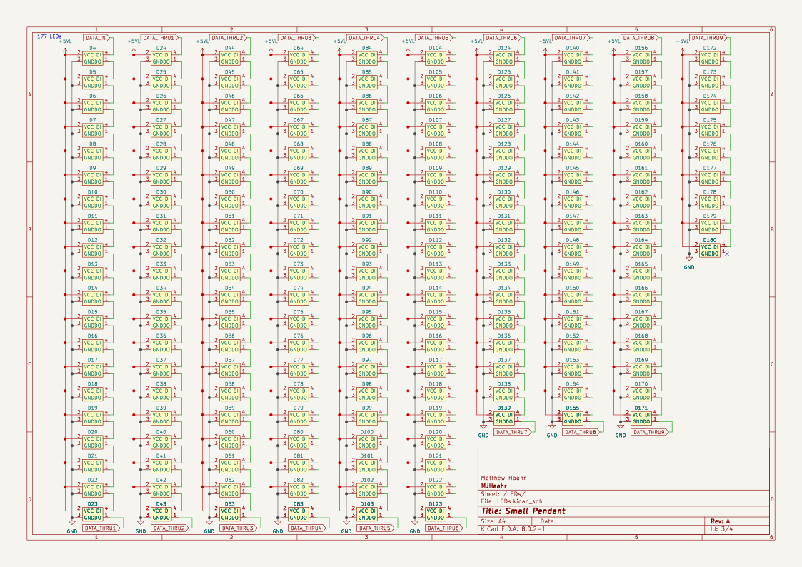
Small RGB LED Pendant using 1010 (1.0x1.0mm) WS2812B LEDs powered by an ESP32-C3 Mini with a BNO055 IMU
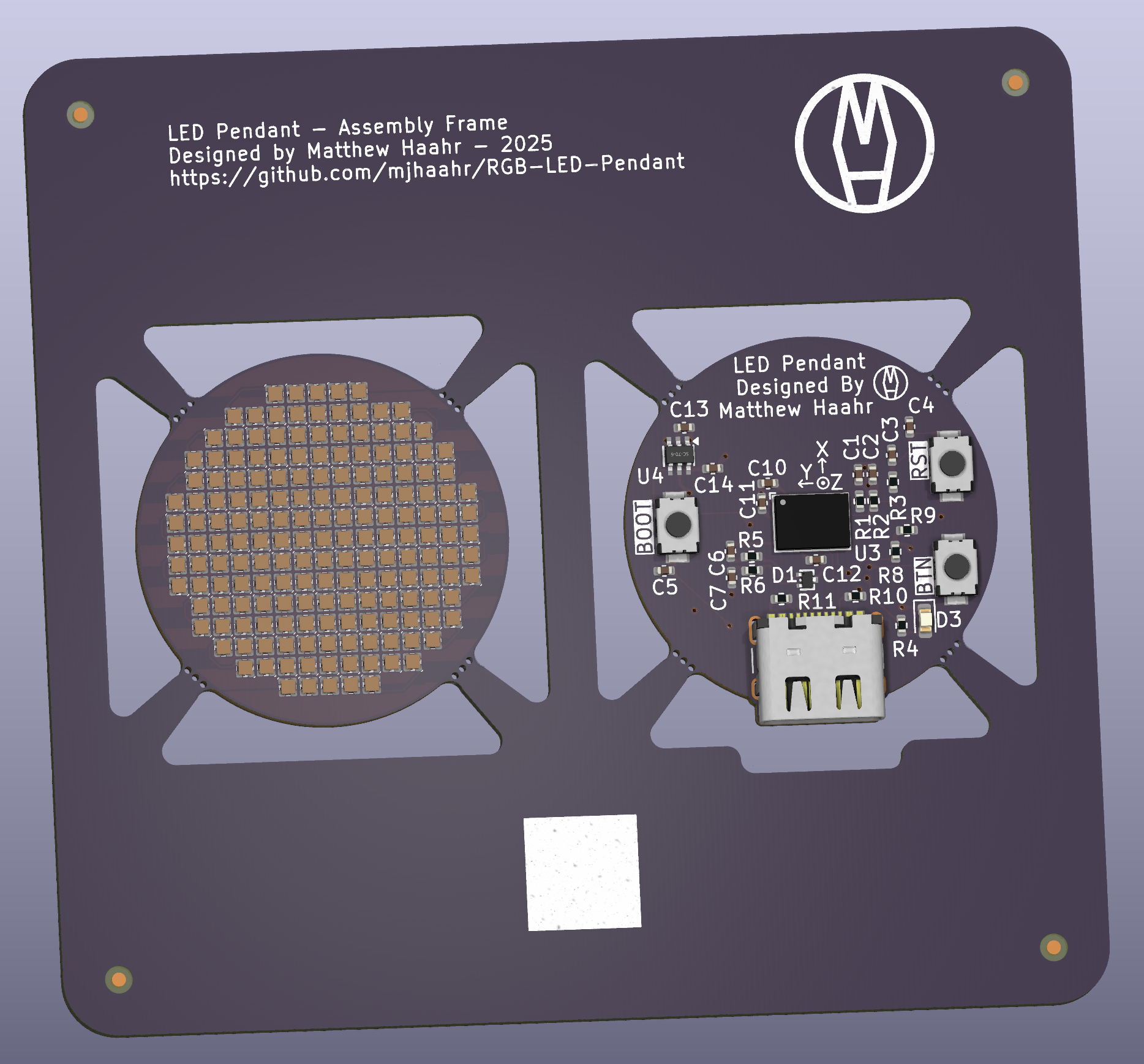
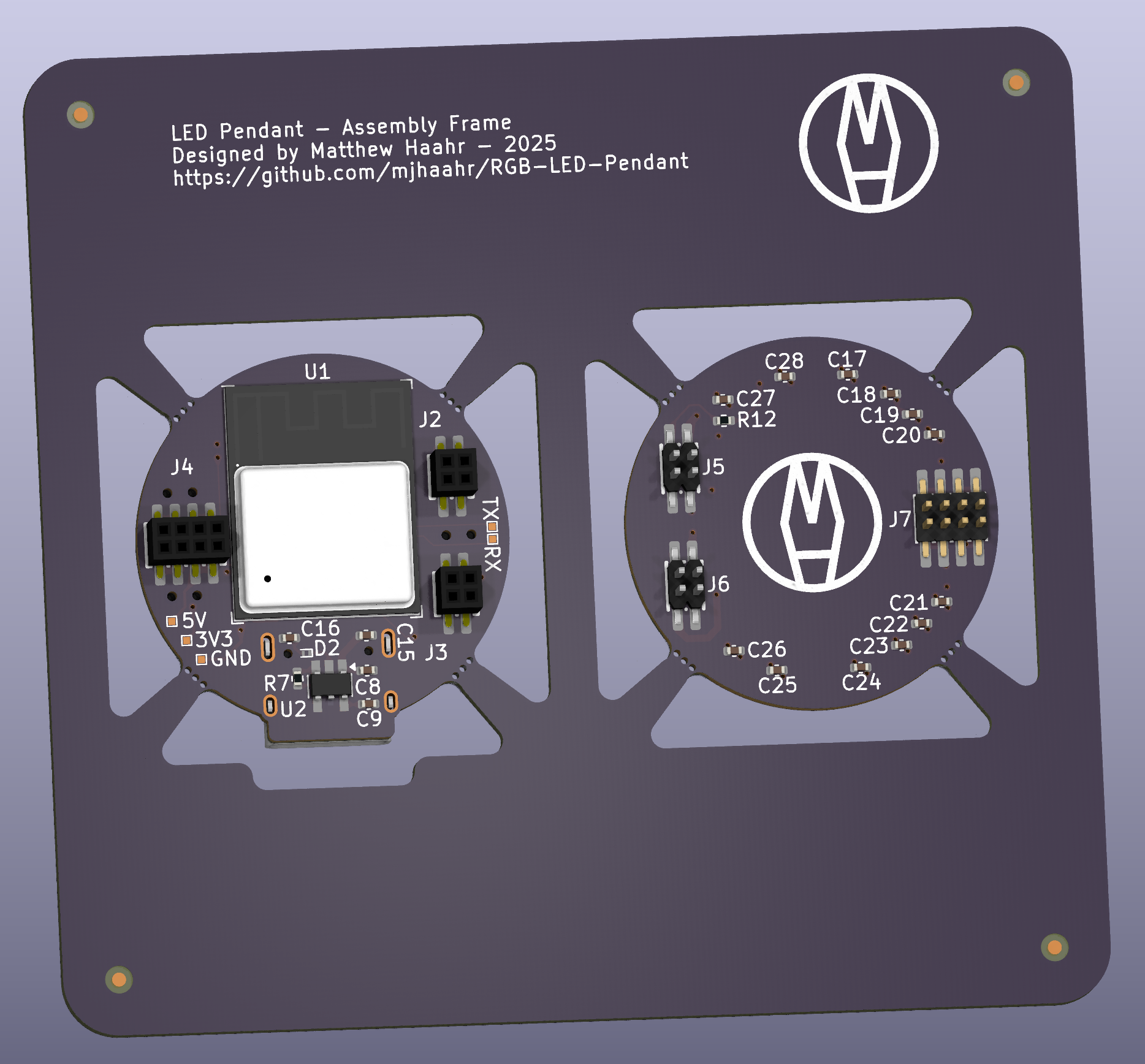
Small Pendant is an open-source printed circuit board by mjhaahr, from the mjhaahr/RGB-LED-Pendant repository on GitHub, published under the MIT licence. It is a 4-layer board of 75 × 70 mm with 260 parts on 245 nets, routed with 564 tracks and 91 vias.
It is built around the ESP32-C3-MINI-1, AP2112K-3.3 and BNO055, with the SN74LVC1T45DCK, XL-1010RGBC-WS2812B-DZ and ESD441DPLR among its other parts. Its parts include 180 diodes, 28 capacitors, 13 resistors, 7 connectors and 4 ICs. It belongs with the lEDs and displays and radio and wireless boards and the ESP32 and RISC-V boards of this library.


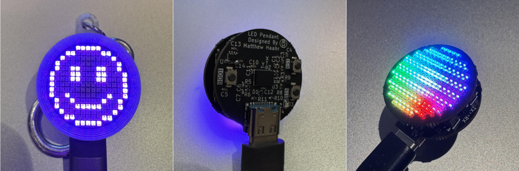
Features:
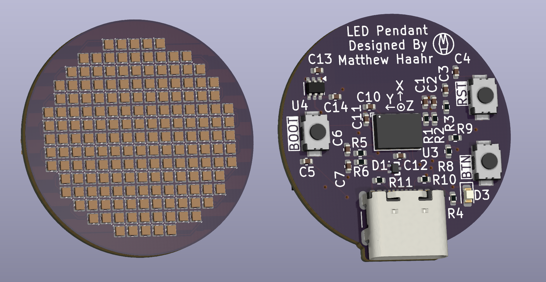
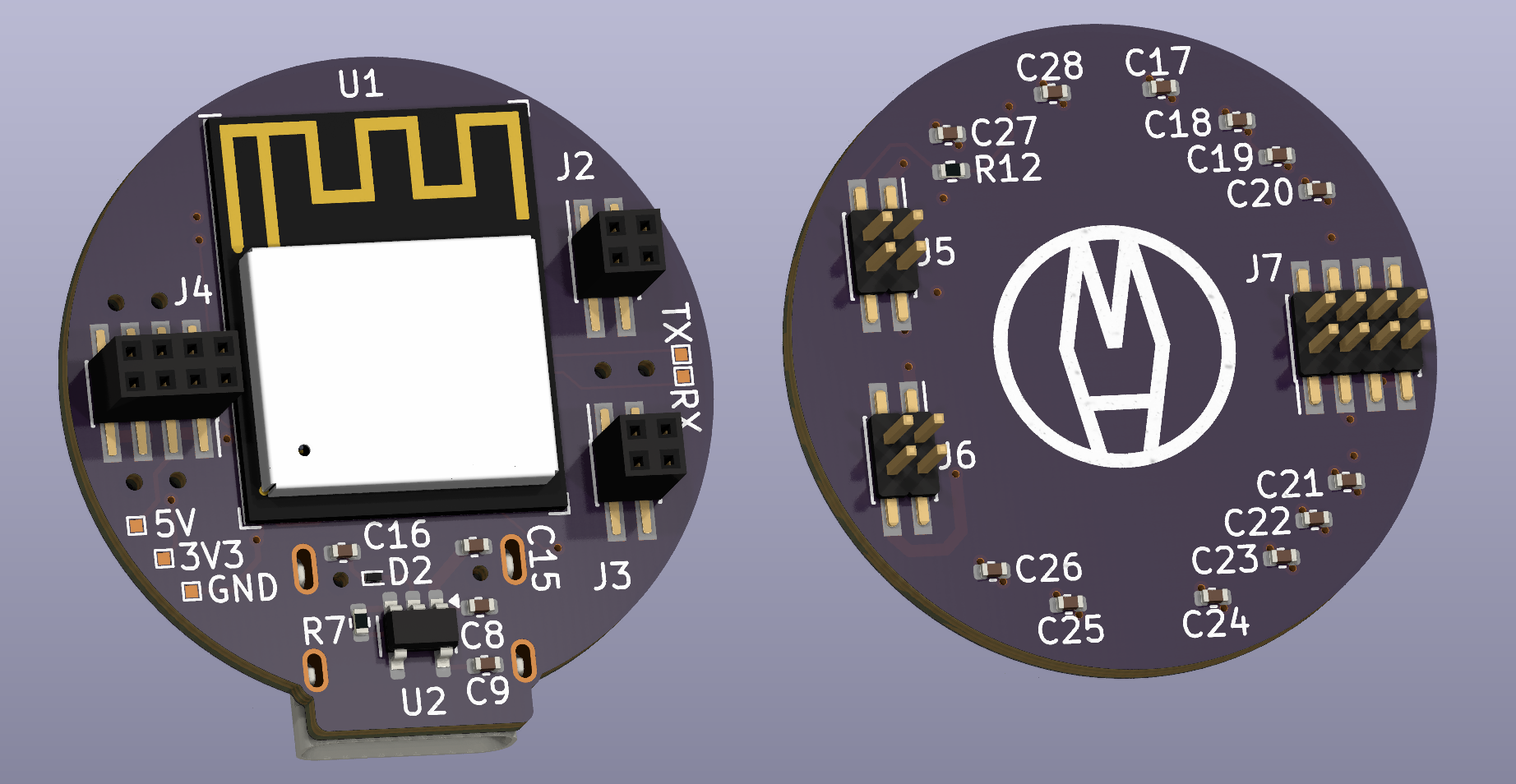
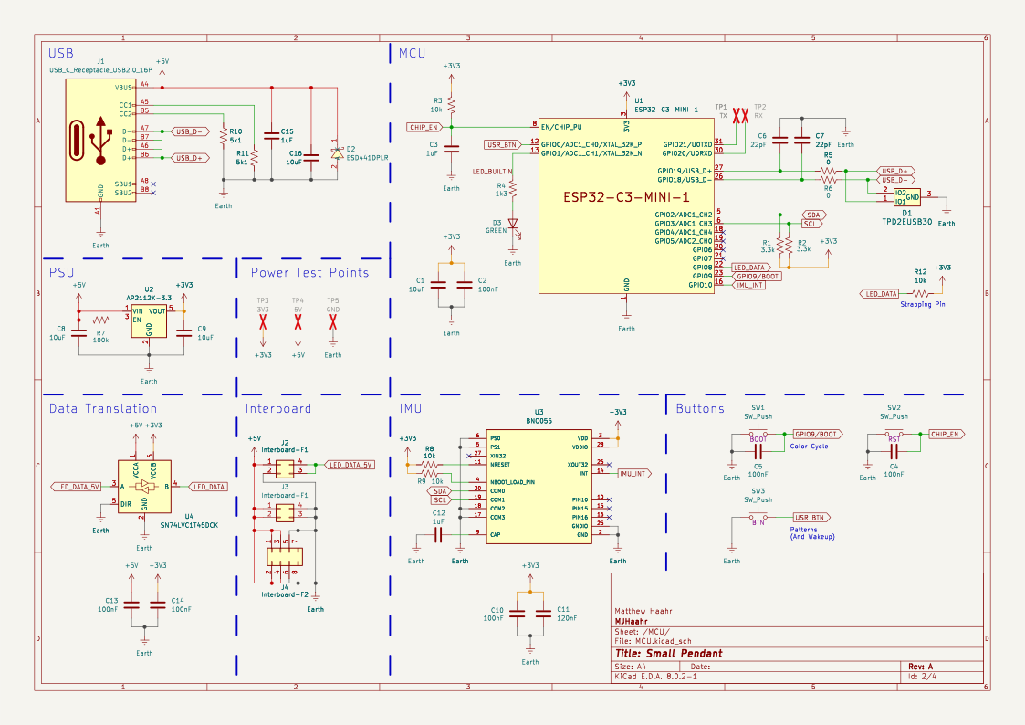
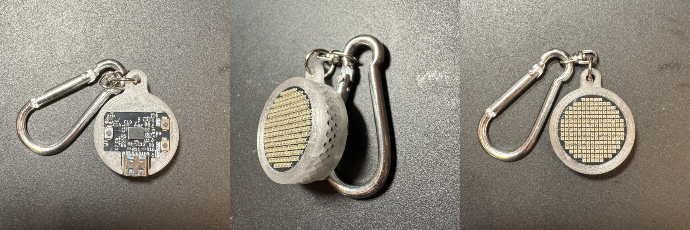
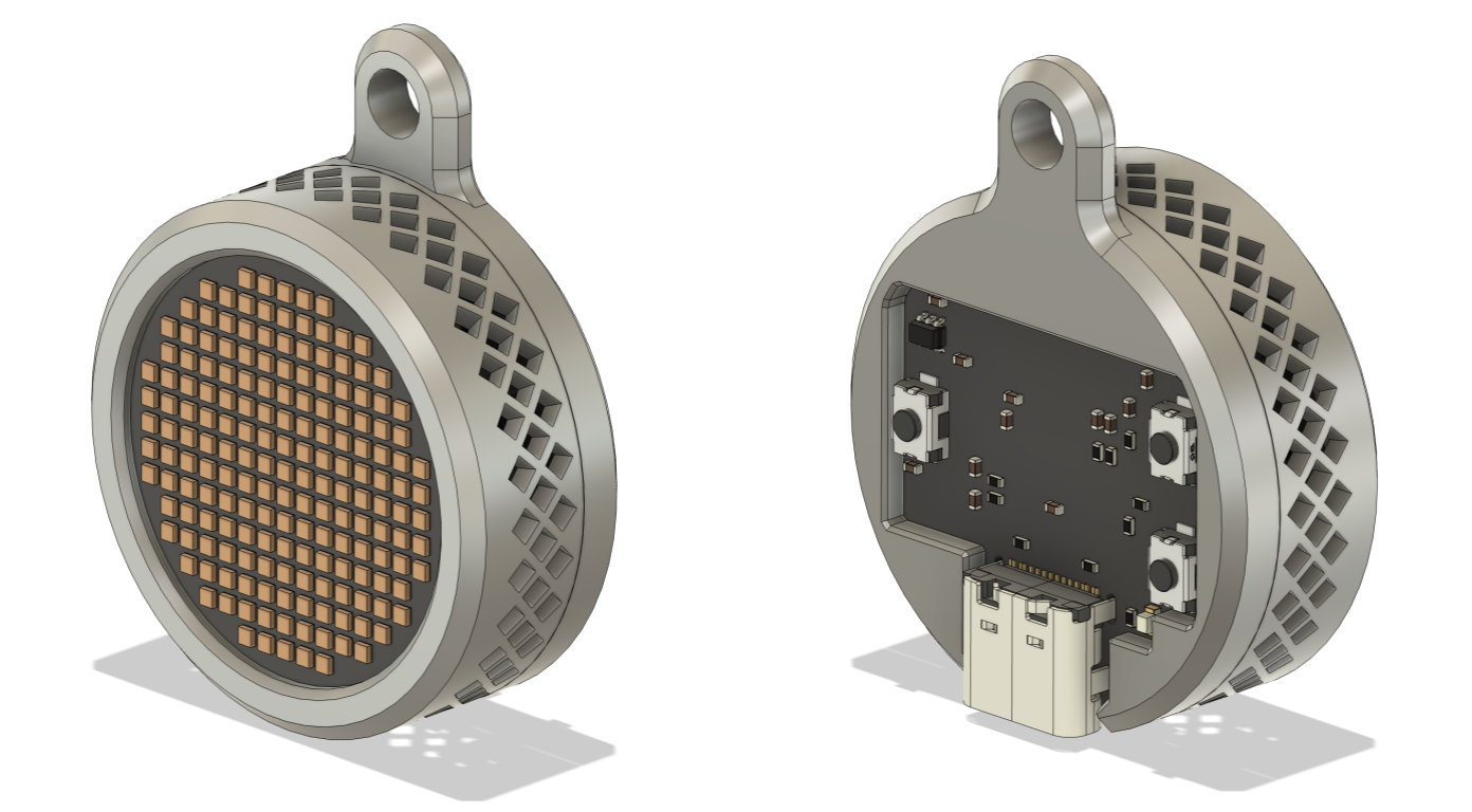
LED_Data) and 6 (3V3) of U4| Qty | Value | Footprint | References |
|---|---|---|---|
| 177 | XL-1010RGBC-WS2812B | LED_SMD:XINGLIGHT-XL-1010RGBC | D10, D11, D100, D101, D102, D103, D104, D105, D106, D107, D108, D109, D110, D111, D112, D113 +161 |
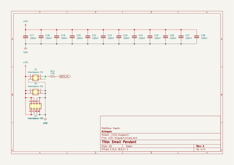
| 18 | 100nF | Capacitor_SMD:C_0402_1005Metric | C2, C10, C13, C14, C17, C18, C19, C20, C21, C22, C23, C24, C25, C26, C27, C28 +2 |
| 8 | VAL** | Panelization:mouse-bite-2mm-slot_round | mouse-bite-2mm-slot, mouse-bite-2mm-slot, mouse-bite-2mm-slot, mouse-bite-2mm-slot, mouse-bite-2mm-slot, mouse-bite-2mm-slot, mouse-bite-2mm-slot, mouse-bite-2mm-slot |
| 4 | 10k | Resistor_SMD:R_0402_1005Metric | R3, R8, R9, R12 |
| 4 | 10uF | Capacitor_SMD:C_0402_1005Metric | C1, C8, C9, C16 |
| 4 | LOGO | Graphics:Logo | G***, G***, G***, G*** |
| 3 | 1uF | Capacitor_SMD:C_0402_1005Metric | C3, C12, C15 |
| 3 | SW_Push | EasyEDA2KiCad:KEY-SMD_L3.9-W3.0-LS5.0-EH | SW1, SW2, SW3 |
| 2 | 0 | Resistor_SMD:R_0402_1005Metric | R5, R6 |
| 2 | 22pF | Capacitor_SMD:C_0402_1005Metric | C6, C7 |
| 2 | 3.3k | Resistor_SMD:R_0402_1005Metric | R1, R2 |
| 2 | 5k1 | Resistor_SMD:R_0402_1005Metric | R10, R11 |
| 2 | Interboard-F1 | EasyEDA2KiCad:HDR-SMD_4P-P1.27-V-F-R2-C2-LS4.8 | J2, J3 |
| 2 | Interboard-M1 | EasyEDA2KiCad:HDR-SMD_4P-P1.27-V-M-R2-C2-S1.27-LS5.5 | J5, J6 |
| 1 | 100k | Resistor_SMD:R_0402_1005Metric | R7 |
| 1 | 120nF | Capacitor_SMD:C_0402_1005Metric | C11 |
| 1 | 1k3 | Resistor_SMD:R_0402_1005Metric | R4 |
| 1 | 3V3 | TestPoint:TestPoint_Pad_0.5x0.5mm | TP3 |
| 1 | 470 | Resistor_SMD:R_0402_1005Metric | R13 |
| 1 | 5V | TestPoint:TestPoint_Pad_0.5x0.5mm | TP4 |
| 1 | AP2112K-3.3 | EasyEDA2KiCad:SOT-25-5_L2.9-W1.6-P0.95-LS2.8-BL | U2 |
| 1 | BNO055 | EasyEDA2KiCad:LGA-28_L5.2-W3.8-P0.50-BL | U3 |
| 1 | ESD441DPLR | EasyEDA2KiCad:X2SON-2_L0.6-W0.3-P0.35_ESD441DPLR | D2 |
| 1 | ESP32-C3-MINI-1 | EasyEDA2KiCad:WIFIM-SMD_ESP32-C3-MINI-1 | U1 |
| 1 | GND | TestPoint:TestPoint_Pad_0.5x0.5mm | TP5 |
| 1 | GREEN | LED_SMD:LED_0603_1608Metric | D3 |
| 1 | Interboard-F2 | EasyEDA2KiCad:HDR-SMD_8P-P1.27-V-F-R2-C4-LS4.8 | J4 |
| 1 | Interboard-M2 | EasyEDA2KiCad:HDR-SMD_8P-P1.27-V-M-R2-C4-W5.5 | J7 |
| 1 | RX | TestPoint:TestPoint_Pad_0.5x0.5mm | TP2 |
| 1 | SN74LVC1T45DCK | EasyEDA2KiCad:SC-70-6_L2.2-W1.3-P0.65-LS2.2-BR | U4 |
| 1 | TPD2EUSB30 | EasyEDA2KiCad:SOT-723_L1.2-W0.8-P0.80-LS1.2-BR | D1 |
| 1 | TX | TestPoint:TestPoint_Pad_0.5x0.5mm | TP1 |
| 1 | USB_C_Receptacle_USB2.0_16P | EasyEDA2KiCad:USB-C-SMD_G-SWITCH_GT-USB-9010AB | J1 |
The 252 most common of 260 parts.

SirBramble/Loguwu
A slightly modified version of the firmware found in the LogicAnalyzer repository can be found in 03Firmware.


JaphD/Phasetag
Compact nRF54L15 Bluetooth Channel Sounding tag with dual PCB antennas, motion sensing, and rechargeable power management. Designed in KiCad 10.

It measures 75 × 70 mm and has 4 copper layers, 1.6 mm thick.
260 parts, built around the ESP32-C3-MINI-1, AP2112K-3.3, BNO055 and SN74LVC1T45DCK. The full list of its parts is on this page, with links to each part's symbol and footprint where PCBKit's library has them.
From the mjhaahr/RGB-LED-Pendant repository on GitHub, at the commit this page was made from: the board is Small_Pendant/Small_Pendant.kicad_pcb and its schematic Small_Pendant/Capacitors.kicad_sch. PCBKit opens the board in the browser, with nothing to install.
Its repository publishes it under the MIT licence: you may reuse it on that licence's terms (keep the author's notice, and for a copyleft licence share your changes alike).