4 layers161 × 87 mm
MainPCB
rohit-env/minideck-pcb
so I went off and designed a whole cyberdeck pcb, it’s kinda sick, it's a full-on deck with ports, buttons, blinky stuff, and that clean hacker aesthetic.
194 parts

 mircotoll01/butterfly-SOA-driver1
Butterfly SOA Driver
SOA driver is an open-source printed circuit board by mircotoll01, from the mircotoll01/butterfly-SOA-driver repository on GitHub, published under the MIT licence. It is a 2-layer board of 107.5 × 72 mm with 136 parts on 106 nets, routed with 827 tracks and 164 vias.
It is built around the MAX1978ETM, MCP4728-E/UN and RJK0355DSP-HXY, with the SIRC18DP, BAT54 and DMP3037LSS-13-F-VB among its other parts. Its parts include 51 capacitors, 29 resistors, 10 transistors, 6 connectors and 5 ICs.


This is an experimental slave module used to drive a optical devices with a butterfly package and integrated TEC. The driver can be operated from the header connector on the side. The board was initially thought as a Laser Diode driver encased in butterfly packages, which usually integrate both the LD and a Peltier cell. Since there is no standard pinouts in butterfly-type packages, this board routes all its power outputs and inputs to a row of headers, and all butterfly pins are routed to open headers as well, so that it is possible to route different parts of the board to different butterfly pins, whose position is numbered and indicated on silkscreen.
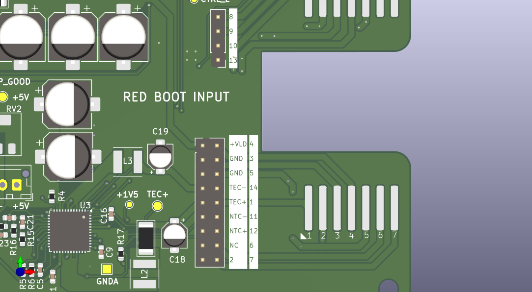
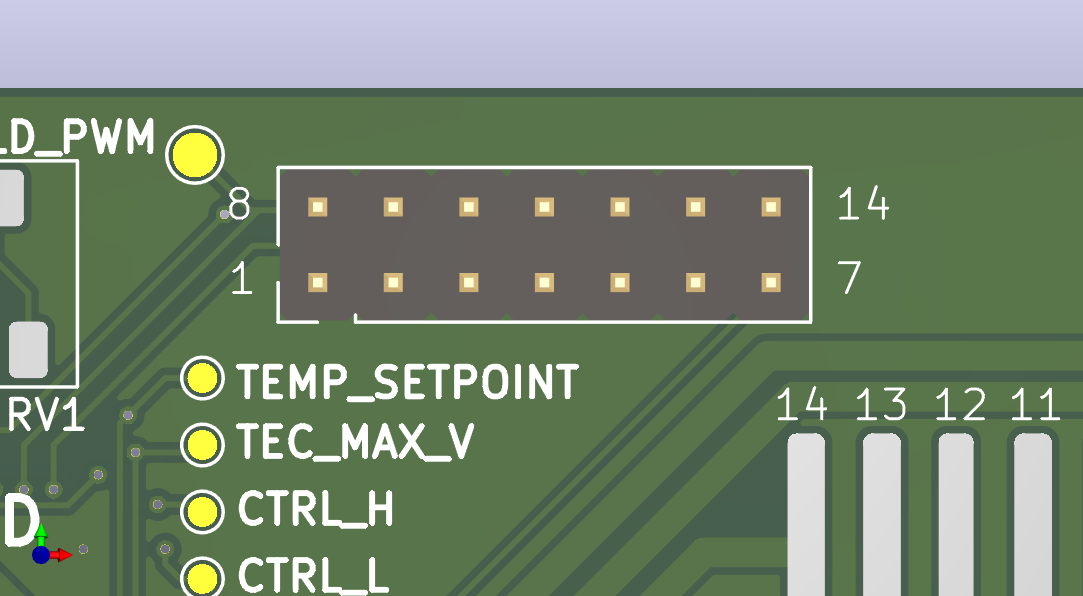
| PIN | USAGE | INFO |
|---|---|---|
| 1 | 3V3 | Logic power supply, mandatory for the DAC that sets the optical device voltage |
| 2 | SCL | I2C clock pin for the DAC |
| 3 | SDA | I2C data pin for the DAC |
| 4 | $\overline{LDAC}$ | Enable DAC register write mode |
| 5 | $RDY/\overline{BSY}$ | This pin gives information on the DAC status |
| 6 | GND | |
| 7 | TEC_EN | Enabling input for TEC |
| 8 | LD_MOD | LT3743's PWM input, when this signal is set to low all switching is disabled. Pull high if you don't plan to use it |
| 9 | CTRL_SEL | LT3743's switch for output voltage selection. The board has a double output capacitor topology that can be used to switch between two voltages. Useful if there is the need to keep an LD under the lasing threshold and periodically switch to a higher voltage. |
| 10 | ILD_MON | optical device current monitor |
| 11 | LD_EN | LT3743's enable pin |
| 12 | UNDRTMP_ALM | Sets if the temperature gets lower than a certain setpoint |
| 13 | OVRTMP_ALM | Sets if the temperature gets higher than a certain setpoint |
| 14 | ITEC_MON | TEC current monitor |
The board was tested with a Basys3 as a master module and the firmware is available in this repository. If a basys3 is used to operate this driver connect its output pins in the following way (declared in the bays3's constraint file):
JA1 → OVRTMP_ALM
JA2 → UNDRTMP_ALM
JA3 → LD_EN
JA4 → CTRL_SEL
JA5 → GND
JA6 → 3V3
JA8 → TEC_EN
JA9 → SDA
JA10 → SCL
JB1 → $\overline{LDAC}$
To control the board with the Basys3 simply connect these pins and connect the board to the computer via USB. The given firmware will provide a rudimental serial interface that will control the state of the driver.
A simple python script can do the trick. the following one will work on linux:
import serial

ser = serial.Serial('/dev/ttyUSB1', baudrate=9600, bytesize=serial.EIGHTBITS, parity=serial.PARITY_NONE, stopbits=serial.STOPBITS_TWO,timeout=10)

while True:
    packet = bytearray(input("Waiting for a command: ").encode("ascii") + b'\n')

    ser.write(packet)

    for i in packet:
        print(ser.read())
Now this repo provides a python script that gives a console to the user to send commands and see current parameters. The requirements for the python script are the following:
| COMMAND | INFO |
|---|---|
| OFF | Pulls LD_EN to low, disables all switching functions. Any other command will set LD_EN back to high |
| CCC | Activates the part of the circuit that supplies costant current to the optical component |
| TEC | Activates the Thermo-Electric Controller |
| PWM | Sets PWM mode with a certain duty cycle, set CTLL voltage first to operate the optical device in this mode |
| SET | Sets the selected register of the DAC to a set value |
| DBL | Sets double output voltage mode, the low and high thresholds have to be set first |
The SET command will accept the following attributes:
| ATTRIBUTE | INFO |
|---|---|
| CTLL | Modifies the lower voltage threshold CTRL_L. Note: this pin is internally clamped to 1.5V by the LT3743 |
| CTLH | Modifies the higher voltage threshold CTRL_H. Note: this pin is internally clamped to 1.5V by the LT3743 |
| TSET | Sets the voltage setpoint for the TEC's PID controller |
| MAXV | Sets the TEC's maximum operating voltage |
| BASE COMMAND | FIRST ATTRIBUTE | SECOND ATTRIBUTE |
|---|---|---|
| OFF | None | None |
| CCC | ON/OFF | None |
| TEC | ON/OFF | None |
| SET | CTLL | Integer from 0 to 1500, which corresponds to a voltage output from the DAC that goes from 0 to 1.5V. This voltage sets the inductor current which charges its corresponding output capacitor. |
| CTLH | ||
| TSET | Integer from 0 to 1500, which corresponds to a voltage output from the DAC that goes from 0 to 1.5V. | |
| MAXV | Integer from 0 to 5000. The program scales it down to reach a voltage output from the DAC that goes from 0 to 1.250V. Since TEC voltage is set to 4*MAXV the range 0-5V range can be achieved. | |
| PWM | Integer encoded in three ciphers from 000 to 100 | None |
| DBL | Integer encoded in three ciphers from 000 to 100 | None |
The commands are not case sensitive anymore
Turn on a SOA or an LD:
CCC ON
PWM 100
Enable PWM modulation
CCC ON
PWM XXX
Enable double threshold modulation
CCC ON
DBL XXX| Qty | Value | Footprint | References |
|---|---|---|---|
| 8 | 330u | Capacitor_SMD:CP_Elec_8x10.5 | C15, C20, C22, C25, C26, C27, C53, C55 |
| 7 | 100n | Capacitor_SMD:C_0603_1608Metric | C1, C3, C32, C34, C44, C45, C46 |
| 7 | TestPoint | TestPoint:TestPoint_Pad_D1.5mm | TP3, TP4, TP5, TP6, TP7, TP14, TP15 |
| 6 | 100n | Capacitor_SMD:C_0805_2012Metric | C4, C14, C29, C39, C43, C49 |
| 5 | TestPoint | TestPoint:TestPoint_Pad_D1.0mm | TP1, TP8, TP9, TP10, TP11 |
| 4 | 10n | Capacitor_SMD:C_0603_1608Metric | C2, C9, C30, C33 |
| 4 | 1k | Resistor_SMD:R_0603_1608Metric | R4, R10, R27, R29 |
| 4 | 1u | Capacitor_SMD:C_0805_2012Metric | C12, C28, C38, C50 |
| 4 | MountingHole | MountingHole:MountingHole_3.2mm_M3_ISO7380 | H1, H2, H3, H4 |
| 4 | RJK0355DSP | Package_SO:SOP-8_3.9x4.9mm_P1.27mm | Q1, Q2, Q9, Q10 |
| 4 | SiRC18DP | Package_SO:PowerPAK_SO-8_Single | Q3, Q4, Q5, Q6 |
| 3 | 10 | Resistor_SMD:R_0603_1608Metric | R11, R14, R28 |
| 3 | 10k | Resistor_SMD:R_0603_1608Metric | R17, R21, R22 |
| 3 | 10u | Capacitor_SMD:C_0603_1608Metric | C11, C13, C23 |
| 3 | 1u | Capacitor_SMD:CP_Elec_4x5.4 | C18, C19, C40 |
| 3 | 4u7 | Capacitor_SMD:C_0603_1608Metric | C16, C41, C42 |
| 3 | NetTie_2 | NetTie:NetTie-2_SMD_Pad0.5mm | NT1, NT2, NT3 |
| 2 | 10u | Capacitor_SMD:C_0805_2012Metric | C37, C51 |
| 2 | 1u | Capacitor_SMD:C_0603_1608Metric | C5, C31 |
| 2 | 2.2n | Capacitor_SMD:C_0603_1608Metric | C6, C7 |
| 2 | 20k | Resistor_SMD:R_0603_1608Metric | R2, R5 |
| 2 | 220u | Capacitor_SMD:CP_Elec_8x10.5 | C35, C36 |
| 2 | 22u | Capacitor_SMD:C_0603_1608Metric | C8, C10 |
| 2 | 22u | Inductor_SMD:L_Taiyo-Yuden_NR-80xx | L1, L4 |
| 2 | 2k2 | Resistor_SMD:R_0603_1608Metric | R9, R20 |
| 2 | 3u3 | Inductor_SMD:L_Taiyo-Yuden_NR-50xx | L2, L3 |
| 2 | 470n | Capacitor_SMD:C_0603_1608Metric | C21, C24 |
| 2 | 806k | Resistor_SMD:R_0603_1608Metric | R7, R8 |
| 2 | BAT54 | Diode_SMD:D_SOD-323F | D1, D3 |
| 2 | R_Small | Resistor_SMD:R_0603_1608Metric | R24, R25 |
| 2 | SolderJumper_2_Open | Jumper:SolderJumper-2_P1.3mm_Open_TrianglePad1.0x1.5mm | JP1, JP2 |
| 1 | 100 | Capacitor_SMD:C_2220_5750Metric_Pad1.97x5.40mm_HandSolder | FB2 |
| 1 | 100k | Resistor_SMD:R_0603_1608Metric | R18 |
| 1 | 100k 1% | Resistor_SMD:R_0603_1608Metric | R23 |
| 1 | 10k | PCM_Potentiometer_SMD_AKL:Potentiometer_Bourns_3224X_Vertical | RV2 |
| 1 | 110R | PCM_Ferrite_SMD_AKL:Ferrite_0805_2012Metric | FB1 |
| 1 | 11K 0.1% | Resistor_SMD:R_0603_1608Metric | R19 |
| 1 | 1M | Resistor_SMD:R_0603_1608Metric | R16 |
| 1 | 1k | PCM_Potentiometer_SMD_AKL:Potentiometer_Bourns_3224X_Vertical | RV1 |
| 1 | 200m | PCM_Resistor_SMD_AKL:R_2010_5025Metric | R12 |
| 1 | 22k | Resistor_SMD:R_0603_1608Metric | R15 |
| 1 | 2N7002 | Package_TO_SOT_SMD:TSOT-23 | Q8 |
| 1 | 33n | Capacitor_SMD:C_0603_1608Metric | C17 |
| 1 | 40.2k | Resistor_SMD:R_0603_1608Metric | R3 |
| 1 | 50m | PCM_Resistor_SMD_AKL:R_2010_5025Metric | R13 |
| 1 | 5V EXT | Connector_JST:JST_XH_B2B-XH-AM_1x02_P2.50mm_Vertical | J6 |
| 1 | 5k6 | Resistor_SMD:R_0603_1608Metric | R26 |
| 1 | 69.8k | Resistor_SMD:R_0603_1608Metric | R1 |
| 1 | 80.6k | Resistor_SMD:R_0603_1608Metric | R6 |
| 1 | BASYS3 | Connector_PinHeader_2.54mm:PinHeader_2x07_P2.54mm_Vertical | J1 |
| 1 | BUTTERFLY | footprints:Butterfly_14pins_SMD | J2 |
| 1 | Barrel_Jack_Switch | Connector_BarrelJack:BarrelJack_Wuerth_6941xx301002 | J3 |
| 1 | DMP3037LSS-13 | Package_SO:SOIC-8_3.9x4.9mm_P1.27mm | Q7 |
| 1 | INA333xxDGK | Package_SO:VSSOP-8_3.0x3.0mm_P0.65mm | U4 |
| 1 | LED | LED_SMD:LED_0603_1608Metric | D2 |
| 1 | LT3743 | Package_SO:TSSOP-28-1EP_4.4x9.7mm_P0.65mm_EP2.85x6.7mm | U2 |
| 1 | MAX1978 | Package_DFN_QFN:TQFN-48-1EP_7x7mm_P0.5mm_EP5.1x5.1mm | U3 |
| 1 | MCP4728 | Package_SO:MSOP-10_3x3mm_P0.5mm | U1 |
| 1 | MIC2101 | Package_DFN_QFN:HVQFN-16-1EP_3x3mm_P0.5mm_EP1.5x1.5mm | U5 |
| 1 | SELECTOR | Connector_PinHeader_2.54mm:PinHeader_2x09_P2.54mm_Vertical | J4 |
| 1 | SELECTOR_2 | Connector_PinHeader_2.54mm:PinHeader_1x04_P2.54mm_Vertical | J5 |
| 1 | TestPoint | TestPoint:TestPoint_Pad_1.5x1.5mm | TP2 |
| 1 | TestPoint | TestPoint:TestPoint_Pad_2.5x2.5mm | TP12 |
| 1 | TestPoint | TestPoint:TestPoint_Pad_1.0x1.0mm | TP13 |
rohit-env/minideck-pcb
so I went off and designed a whole cyberdeck pcb, it’s kinda sick, it's a full-on deck with ports, buttons, blinky stuff, and that clean hacker aesthetic.

wntrblm/jellyfish-and-starfish
Jellyfish and Starfish are control boards designed for use with the LumenPnP. Starfish controls the base of the machine including X & Y axes and pneumatics.

nunosousa/SCART-switcher
An old school SCART switcher. Its main purpose will be to automaticaly detect and switch the video output to the active input video source.

nunosousa/TelescopeMirrorTester
This is an application intended to provide useful tools to perform Foucault or Wire testing on reflective telescope mirrors


CrashOverride85/zc95
4 channel EStim box inspired by the mk312bt, with Lua scripting support

thebiguno/microcontroller-projects
A home for a bunch of microcontroller projects which don't warrant their own repos.

DanielMartensson/STM32-Ethernet-Camera
PCB board with camera and ethernet connection + CAN-bus
It measures 107.5 × 72 mm and has 2 copper layers, 1.6 mm thick.
136 parts, built around the MAX1978ETM, MCP4728-E/UN, RJK0355DSP-HXY and SIRC18DP. The full list of its parts is on this page, with links to each part's symbol and footprint where PCBKit's library has them.
From the mircotoll01/butterfly-SOA-driver repository on GitHub, at the commit this page was made from: the board is hardware/SOA-driver.kicad_pcb and its schematic hardware/SOA-driver.kicad_sch. PCBKit opens the board in the browser, with nothing to install.
Its repository publishes it under the MIT licence: you may reuse it on that licence's terms (keep the author's notice, and for a copyleft licence share your changes alike).