
2 layers333.4 × 149.9 mm

 mignon-p/NeoBit6
KiCad files for a board that lets you hook up NeoPixels to a BBC micro:bit. The board also has a couple of slide potentiometers for input.
NeoBit is an open-source printed circuit board by mignon-p, from the mignon-p/NeoBit repository on GitHub, published under the CC-BY-SA-4.0 licence. It is a 2-layer board of 77.5 × 45.7 mm with 27 parts on 21 nets, routed with 184 tracks and 26 vias.
It is built around the 74AHCT125D. Its parts include 10 capacitors, 6 connectors, 3 resistors, 3 ICs and 1 diode. It belongs with the lEDs and displays boards of this library.
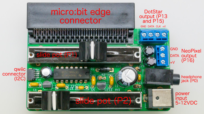
The neo:bit is a board which attaches to the edge connector of the BBC micro:bit and provides:
Two slide potentiometers, connected to micro:bit pins P1 and P2, which can be read as analog inputs.
A terminal block for connecting "NeoPixels" (WS-2812 LEDs), with a level shifter to convert from 3.3V logic (on pin P16) to 5V logic.
A terminal block for connecting "DotStars" (APA-102 LEDs), with a level shifter to convert from 3.3V logic (on pins P13 and P15) to 5V logic.
A Qwiic connector for attaching I2C peripherals.
A 3.5mm audio jack for headphones. (Connected to pin P0).
A barrel connector for an external 5-12V power supply, which is mandatory for powering the NeoPixels, and can also optionally backpower the micro:bit safely.
This repository contains KiCad and gerber files for the neo:bit board.
Note that the voltage which comes in on the barrel jack is used directly to power the NeoPixels and DotStars, so you need to choose a voltage which is appropriate for the NeoPixels and/or DotStars you are using. Most NeoPixels are 5V, although there are a few 12V ones. I don't know of any DotStars which are not 5V. You can't have a different voltage for the NeoPixels and the DotStars.
The neo:bit contains a low-dropout 3.3V voltage regulator, which is used for back-powering the micro:bit, and for supplying the 3.3V power on the Qwiic connector. You probably shouldn't draw more than 90 mA on the Qwiic connector's power pin.
The neo:bit also contains a low-dropout 5V voltage regulator, but that is just to supply the 5V signal on the NeoPixel and DotStar data lines.
To read the slide potentiometers, just configure P1 and P2 as analog inputs, and read them. The idea is that you could use these inputs to control your NeoPixel animation, such as the speed, color, or brightness.
J4 has the NeoPixel output, along with +V and GND. You may want to connect a JST-SM pigtail to the J4 screw terminals. This will let you connect strings of 5V NeoPixels, such as ones from Alitove or Wesiri, or my chainable NeoPixel butterflies. (The Wesiri lights come with the necessary pigtail, so you don't need to buy one separately.)
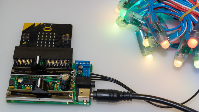
You must have an external power supply (such as this one or this one for 5V, or this one for 12V) connected to the neo:bit's barrel jack in order to power the NeoPixels. If the external power supply is connected, the neo:bit will also supply 3.3V back to the micro:bit, so it is not necessary to power the micro:bit from another source. (However, this is done with a protection diode, so it is OK to have the micro:bit connected to another source at the same time the external supply is connected.) If you only want to use the potentiometers and/or Qwiic but not the NeoPixel output or DotStar output, then you do not need to have an external supply connected, as long as the micro:bit is powered by another source.
Following the NeoPixel best practices, the neo:bit includes a 470 ohm resistor on the NeoPixel data line, and there is a 1000µF capacitor on the +V power line.
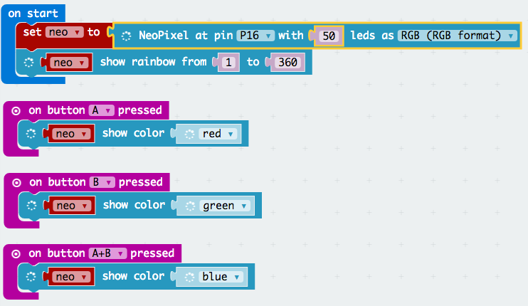
Once you have your NeoPixels hooked up, you should be able to access them by instantiating a NeoPixel strip on pin P16 in either MakeCode or Python. The Alitove and Wesiri strings, as well as my NeoPixel butterflies, use RGB order instead of the default GRB order.
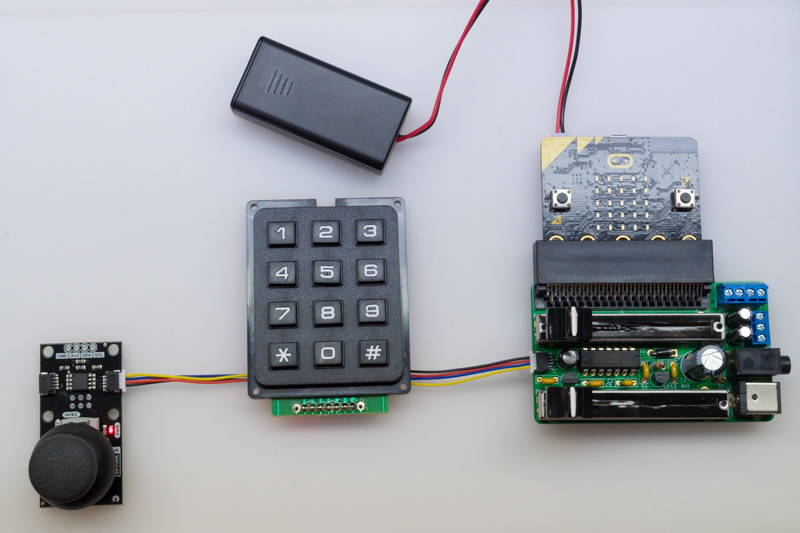
I have an example for how to use the Qwiic Keypad, and another example for how to use the Qwiic Joystick.
You can order this board directly from OSH Park without needing to upload anything.
Or, if you prefer to go with another fab like Elecrow or
JLCPCB, all you need to do is zip up the files in the gerber
directory, and upload that zip file to the fab.
If you want to modify the design, the source is provided in KiCad format.
| Ref | Description | MPN | Digi-Key PN |
|---|---|---|---|
| C1 | CAP ALUM 1000UF 20% 25V RADIAL | 25PX1000MEFCT810X16 | 1189-1583-1-ND |
| C2 | CAP CER 0.1UF 50V X7R RADIAL | K104K10X7RF5UH5 | BC2665CT-ND |
| C3-C6 | CAP CER 1UF 50V Y5V RADIAL | K105Z20Y5VF5TH5 | BC1168CT-ND |
| C7 | CAP ALUM 47UF 20% 16V RADIAL | ECE-A1CKS470 | P969-ND |
| C8, C9 | CAP ALUM 220UF 20% 10V RADIAL | UVK1A221MDD1TD | 493-7455-1-ND |
| C10 | CAP CER 10000PF 50V X7R RADIAL | K103K15X7RF5TL2 | BC1078CT-ND |
| D1 | DIODE SCHOTTKY 20V 1A DO41 | 1N5817 | 1N5817FSCT-ND |
| J1 | CONN JACK STEREO 3.5MM R/A | SJ1-3533NG | CP1-3533NG-ND |
| J2 | CONN PWR JACK 2X5.5MM SOLDER | PJ-063AH | CP-063AH-ND |
| J3 | Qwiic JST Connector - SMD 4-pin | PRT-14417 | (SparkFun) |
| J4 | TERM BLOCK 4POS SIDE ENT 3.5MM | 1776275-4 | A98038-ND |
| J5 | micro:bit through-hole right-angle edge connector | 3342 | (Adafruit) |
| J6 | TERM BLOCK 3POS SIDE ENT 3.5MM | 1776275-3 | A98037-ND |
| R1 | RES 100 OHM 1/4W 5% AXIAL | CF14JT100R | CF14JT100RCT-ND |
| R2 | RES 470 OHM 1/4W 5% AXIAL | CF14JT470R | CF14JT470RCT-ND |
| R3 | RES 22 OHM 1/4W 5% AXIAL | CF14JT22R0 | CF14JT22R0CT-ND |
| RV1, RV2 | SLIDE POT 10K OHM 0.25W TOP 45MM | PTA4553-2015CPB103 | PTA4553-2015CPB103-ND |
| U1 | IC BUF NON-INVERT 5.5V 14DIP | SN74AHCT125N | 296-4655-5-ND |
| U2 | IC REG LINEAR 3.3V 250MA TO92-3 | MCP1702-3302E/TO | MCP1702-3302E/TO-ND |
| U3 | IC REG LINEAR 5V 250MA TO92-3 | MCP1702-5002E/TO | MCP1702-5002E/TO-ND |
| (qty 2) | KNOB SMOOTH 0.157 X 0.039" NYLON | 1300-E | [1722-1329-ND][61] |
Plus you'll need a micro:bit, a power supply (such as this one), and some NeoPixels.
The right-angle micro:bit edge connector (J5) is 4UCON 10156, which is available from Adafruit in the US and from Cool Components in the UK.
Most of the assembly should be straightforward, but there are a few connectors worthy of more discussion.
The four electrical pins are not enough to hold this connector in place. There are two mounting pins which are also meant to be soldered, but I found hand-soldering them was nearly impossible. So, I used a drop of epoxy to hold the Qwiic connector in place.
I've found that stranded wires don't stay in the terminal blocks very well, so I recommend using solid wire. Or, you may wish to omit the terminal blocks entirely and solder wires directly to the board.
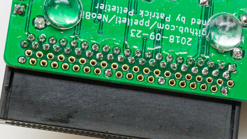
The micro:bit connector has 80 pins, but only 40 of them need to be soldered. The pins that need to be soldered are the two rows farthest from the edge. (These pins are slightly taller than the others.) I usually solder just a few of the pins on the row closest to the edge, too, just for mechanical stability.
The files in this repo are licensed under CC-BY-SA 4.0.
Some symbols and footprints in this repo are under different licenses:
| Qty | Value | Footprint | References |
|---|---|---|---|
| 4 | 1µF | Capacitors_THT:C_Rect_L7.0mm_W2.5mm_P5.00mm | C3, C4, C5, C6 |
| 2 | 10K | footprints:Bourns_PTA4543 | RV1, RV2 |
| 2 | 220uF | Capacitors_THT:CP_Radial_D5.0mm_P2.50mm | C8, C9 |
| 1 | 0.1µF | Capacitors_THT:C_Rect_L7.0mm_W2.5mm_P5.00mm | C2 |
| 1 | 100 | Resistors_THT:R_Axial_DIN0207_L6.3mm_D2.5mm_P2.54mm_Vertical | R1 |
| 1 | 1000µF | Capacitors_THT:CP_Radial_D10.0mm_P5.00mm | C1 |
| 1 | 10nF | Capacitors_THT:C_Disc_D3.8mm_W2.6mm_P2.50mm | C10 |
| 1 | 22 | Resistors_THT:R_Axial_DIN0207_L6.3mm_D2.5mm_P2.54mm_Vertical | R3 |
| 1 | 470 | Resistors_THT:R_Axial_DIN0207_L6.3mm_D2.5mm_P2.54mm_Vertical | R2 |
| 1 | 47µF | Capacitors_THT:CP_Radial_D6.3mm_P2.50mm | C7 |
| 1 | 74AHCT125 | Housings_DIP:DIP-14_W7.62mm | U1 |
| 1 | AudioJack3_Ground | footprints:SJ1-3533NG | J1 |
| 1 | Barrel_Jack_MountingPin | footprints:BarrelJack_CUI_PJ-063AH_Horizontal_CircularHoles | J2 |
| 1 | D_Schottky | Diodes_THT:D_DO-41_SOD81_P7.62mm_Horizontal | D1 |
| 1 | DotStars | footprints:TerminalBlock_4Ucon_1x04_P3.50mm_Vertical | J4 |
| 1 | LOGO | footprints:Fingerprint | G*** |
| 1 | MCP1702-3302E_TO92 | TO_SOT_Packages_THT:TO-92_Inline_Narrow_Oval | U2 |
| 1 | MCP1702-5002E_TO92 | TO_SOT_Packages_THT:TO-92_Inline_Narrow_Oval | U3 |
| 1 | NeoPixels | footprints:TerminalBlock_4Ucon_1x03_P3.50mm_Vertical | J6 |
| 1 | Qwiic | Connectors_JST:JST_SH_SM04B-SRSS-TB_04x1.00mm_Angled | J3 |
| 1 | microbit_edge_connector | footprints:4UCON_10156_2x40_P1.27mm_Socket_Horizontal | J5 |
The 26 most common of 27 parts.
It measures 77.5 × 45.7 mm and has 2 copper layers, 1.6 mm thick.
27 parts, built around the 74AHCT125D. The full list of its parts is on this page, with links to each part's symbol and footprint where PCBKit's library has them.
From the mignon-p/NeoBit repository on GitHub, at the commit this page was made from: the board is NeoBit.kicad_pcb. PCBKit opens the board in the browser, with nothing to install.
Its repository publishes it under the CC-BY-SA-4.0 licence: you may reuse it on that licence's terms (keep the author's notice, and for a copyleft licence share your changes alike).


byungyoonc/TrueStrike42
TrueStrike42 is a columnar staggered unibody split keyboard designed to maximize performance and minimize finger fatigue.

twasilczyk/waterdrop-esphome
Waterdrop RO system smart Wi-Fi module for Home Assistant

usedhondacivic/ECE-4760-POV-Display
Persistence of vision display. 30 FPS, full RGB color, and 26" diameter. Updates remotely over WIFI.

GLGPrograms/tinyDiskII
Homemade floppy disk emulator for Apple II series computers

joshjetson/phosphor
A full fledged DAW in TUI and GUI flavors: Run it in the terminal or run it as a desktop app (Desktop App Coming Soon..maybe)