4 layers74.1 × 130 mm

 Michael-Manning/E-Paper-Climate-Logger457
Firmware, PCB, and enclosure for the Weathergotchi E-Paper climate logger.
Templog mainboard is an open-source printed circuit board by Michael-Manning, from the Michael-Manning/E-Paper-Climate-Logger repository on GitHub, published under the MIT licence. It is a 4-layer board of 45 × 32 mm with 68 parts on 93 nets, routed with 704 tracks and 116 vias.
It is built around the ESP32-S3-MINI-1-N8, TPS62203DBV and 24LC512-I/P, with the BQ24075RGT, DS3231MZ/V+ and USBLC6-2SC6 among its other parts. Its parts include 23 capacitors, 21 resistors, 9 ICs, 3 diodes and 2 connectors. It belongs with the lEDs and displays and computers and single-board computers boards and the ESP32 boards of this library.


This project is an open-source, battery-powered temperature and humidity data logger with an always-on e-paper display. It records ambient conditions over time, stores readings in non-volatile memory, and displays current data along with a history graph. The device is designed for low power consumption, over 2 weeks of operation on a small Li‑Po battery.
Key features:
The entire project is open source, including hardware schematics, PCB layout, firmware, and enclosure CAD files. A detailed build video is available on YouTube: E-Paper Climate Logger.
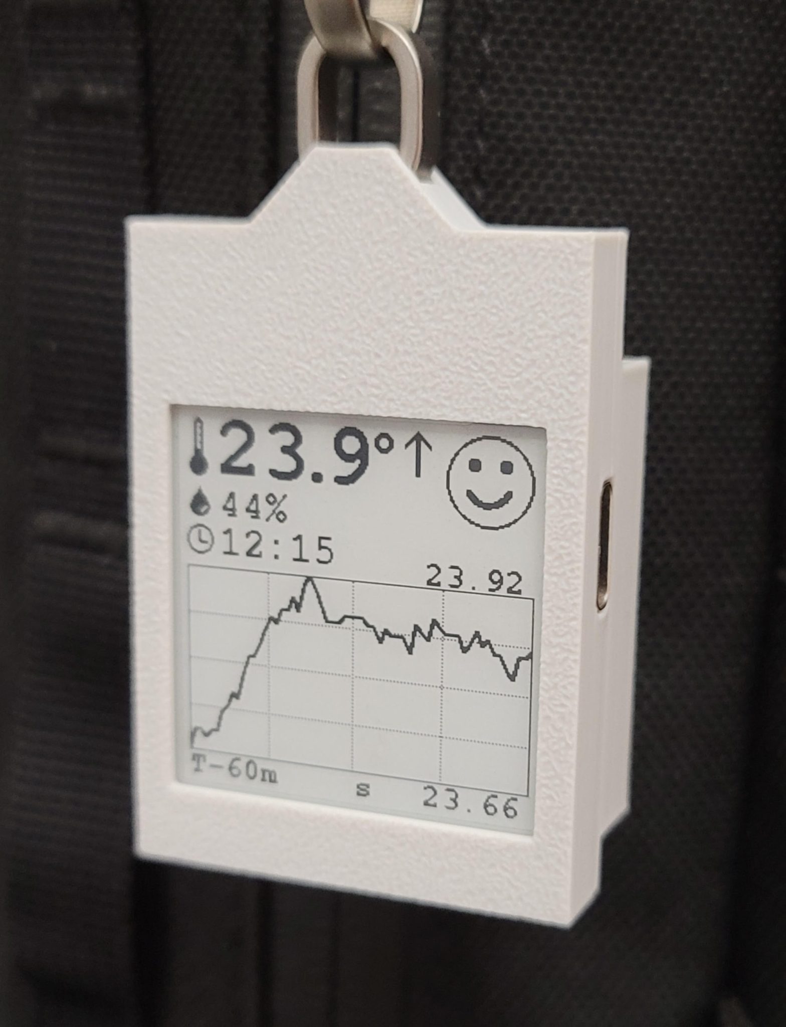
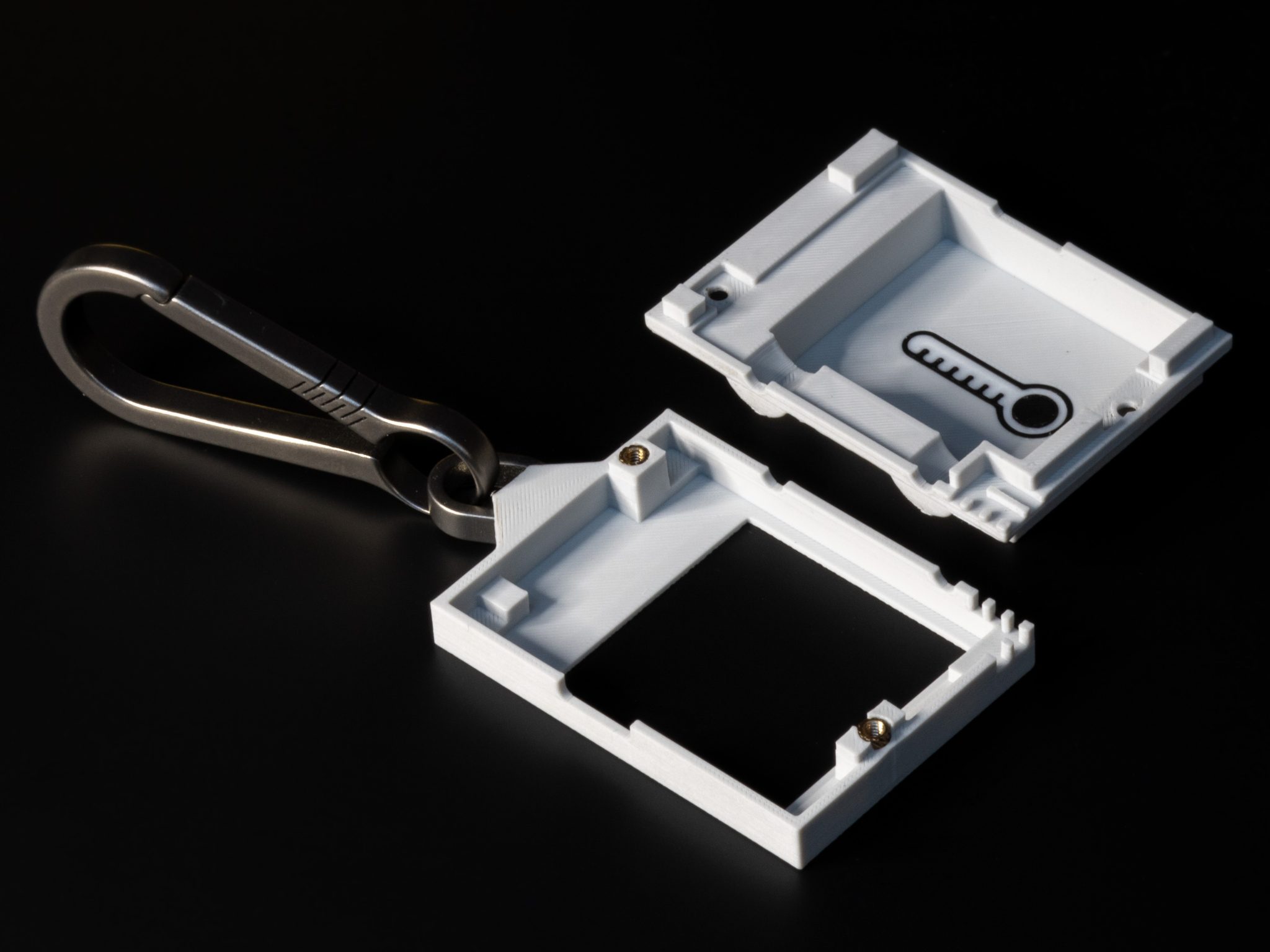
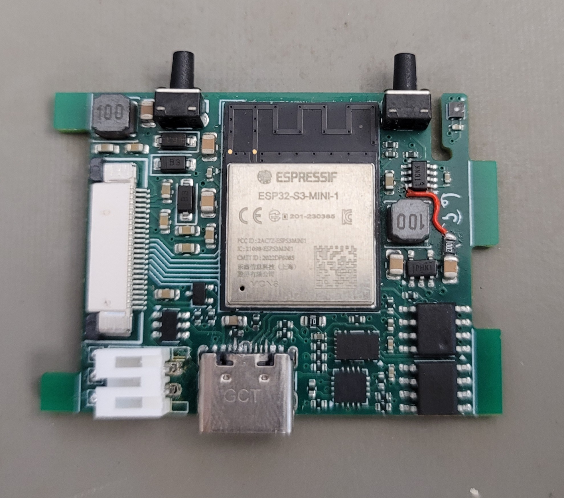
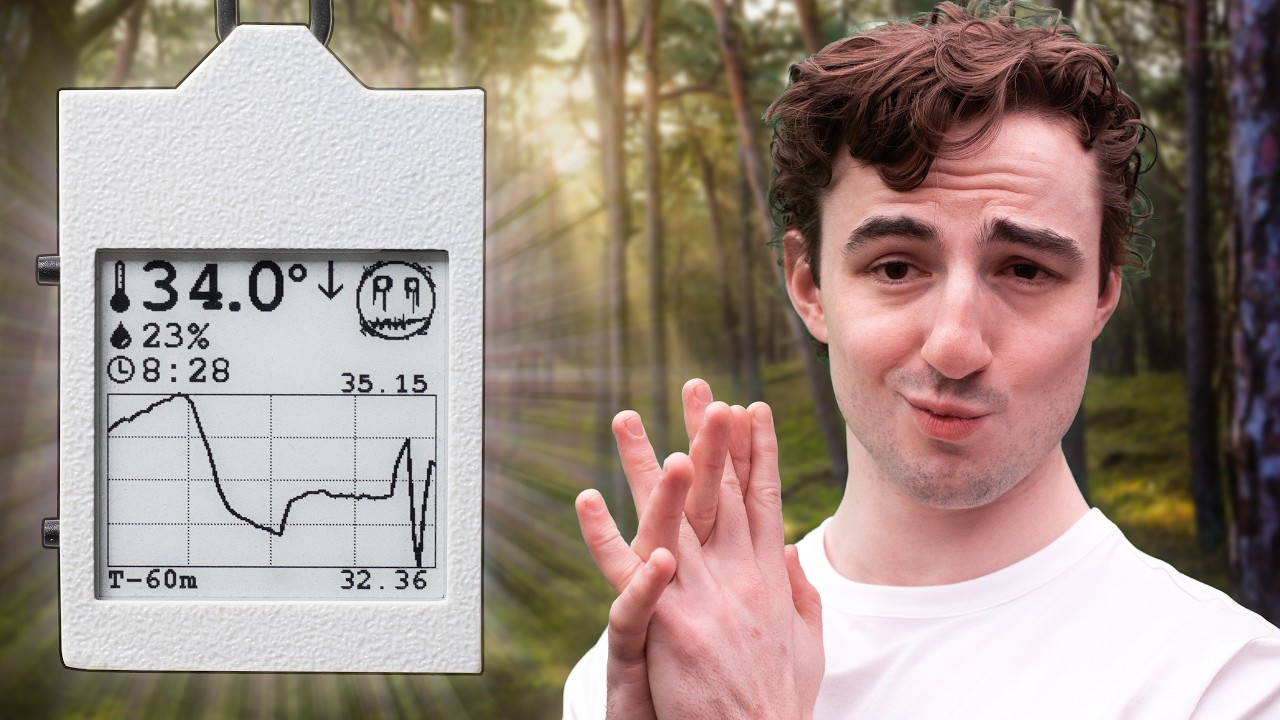
E-Paper-Climate-Logger/
├── CAD/                 # 3D case design (OpenSCAD source and STL exports)
├── PCB/                 # KiCad hardware design, schematics, datasheets, references
├── firmware/            # PlatformIO firmware (ESP32-S3, Arduino framework)
├── LICENSE              # License file
└── README.md # This fileContains the parametric OpenSCAD models for the front and back case halves, assembly files, and exported STLs for 3D printing. The design is fully parametric – dimensions can be adjusted by editing constants.scad.
All hardware design files for the custom mainboard (templog_mainboard). This directory includes:
.kicad_sch, .kicad_pcb, .kicad_pro)To view or modify the PCB design, install KiCad 9 or later and open templog_mainboard.kicad_pro.
PlatformIO project for the ESP32‑S3 using the Arduino framework. It handles sensor reading, timekeeping, data logging to EEPROM, e‑paper display updates, button handling, and power management (deep sleep, wake sources). See firmware/README.md for detailed build and flashing instructions.
CAD/export/)Install PlatformIO Core (or use the PlatformIO extension in VS Code).
Navigate to the firmware directory.
Connect the device via USB‑C.
Run:
pio run --target uploadMonitor serial output (optional):
pio device monitorFor detailed firmware documentation, including folder structure, driver details, and low‑power operation, refer to firmware/README.md.
Print the STL files from CAD/V2/export/ using a high‑resolution FDM printer (0.08 mm layer height recommended). The case uses M2 heat set inserts and M2 screws. Insert the PCB and battery, then screw the front and back halves together. See note.txt in CAD\V2 for more details.
All I2C peripherals (SHT45, DS3231, 24LC512, BQ27441) share the same bus. The e‑paper display is driven via SPI, and the LTC2954 soft power button controls system power-off via the BQ24075.
For complete schematics and PCB layout, open the KiCad project in PCB/templog_mainboard/.
The device is designed to run for over 2 weeks on a small battery:
I don't have a detailed build guide on how to build your own device at this time, but if you do decide to make one, these are some details you should know.
BQ27441.cpp. The fuel gauge also needs to "learn" the battery before it reports an accurate state of charge. Fully charge the battery, then wait for it to completely deplete. This will help the fuel gauge report a more accurate charge level.Issues, pull requests, and suggestions are welcome. Please follow the existing code style and document any changes to the hardware or firmware.
Refer to the LICENSE file in the root directory for licensing terms (open source, permissive).
For questions or discussions, open an issue on GitHub or visit the YouTube video comments.
| Qty | Value | Footprint | References |
|---|---|---|---|
| 14 | 10k | Resistor_SMD:R_0402_1005Metric | R1, R2, R6, R7, R8, R9, R10, R12, R13, R17, R18, R19, R20, R21 |
| 8 | 1uf/50V | Capacitor_SMD:C_0603_1608Metric | C23, C24, C25, C26, C27, C28, C29, C30 |
| 5 | 0.1uf | Capacitor_SMD:C_0402_1005Metric | C1, C3, C4, C5, C14 |
| 5 | 5.1k | Resistor_SMD:R_0402_1005Metric | R3, R4, R11, R14, R15 |
| 3 | 10uf | Capacitor_SMD:C_0805_2012Metric | C2, C9, C10 |
| 3 | MBR0530 | Diode_SMD:D_SOD-123 | D2, D3, D4 |
| 2 | 10uH | Inductor_SMD:L_Sunlord_SWPA4030S | L1, L2 |
| 2 | 1uf | Capacitor_SMD:C_0402_1005Metric | C7, C15 |
| 2 | 4.7uf/50V | Capacitor_SMD:C_0805_2012Metric | C21, C22 |
| 2 | TC-1109DE-C-H | TC-1109DE-C-H:SW-TH_TC-1109DE-C-H | SW1, SW2 |
| 1 | +RESET | TestPoint:TestPoint_Pad_1.0x1.0mm | TP1 |
| 1 | -RESET | TestPoint:TestPoint_Pad_1.0x1.0mm | TP2 |
| 1 | 0.01/1% | Resistor_SMD:R_0603_1608Metric | R5 |
| 1 | 0.47uf | Capacitor_SMD:C_0402_1005Metric | C8 |
| 1 | 1uf | Capacitor_SMD:C_0603_1608Metric | C13 |
| 1 | 24LC512 | Package_SO:SOIC-8_3.9x4.9mm_P1.27mm | U6 |
| 1 | 3 | Resistor_SMD:R_0402_1005Metric | R16 |
| 1 | 4.7uf | Capacitor_SMD:C_0603_1608Metric | C6 |
| 1 | AFC07-S24ECA-00 | FPC-SMD_AFC07-S24ECA-00:FPC-SMD_AFC07-S24ECA-00 | FPC1 |
| 1 | BOOT | TestPoint:TestPoint_Pad_1.0x1.0mm | TP3 |
| 1 | BQ24075RGT | Package_DFN_QFN:VQFN-16-1EP_3x3mm_P0.5mm_EP1.6x1.6mm | U5 |
| 1 | BQ27441-G1 | Package_SON:Texas_S-PDSO-N12 | U4 |
| 1 | DS3231MZ | Package_SO:SOIC-8_3.9x4.9mm_P1.27mm | U2 |
| 1 | ESP32-S3-MINI-1 | RF_Module:ESP32-S2-MINI-1 | U1 |
| 1 | LOGO | LOGO | G*** |
| 1 | LTC2954CTS8-2_TRMPBF | LTC2954CTS8_2_TRMPBF:TSOT-23_TS8 | U9 |
| 1 | SHT4x | Sensor_Humidity:Sensirion_DFN-4_1.5x1.5mm_P0.8mm_SHT4x_NoCentralPad | U3 |
| 1 | Si1308EDL | Package_TO_SOT_SMD:SOT-323_SC-70 | Q1 |
| 1 | TPS62203DBV | Package_TO_SOT_SMD:SOT-23-5 | U8 |
| 1 | USBLC6-2SC6 | Package_TO_SOT_SMD:SOT-23-6 | U7 |
| 1 | USB_C_Receptacle_USB2.0_16P | Connector_USB:USB_C_Receptacle_GCT_USB4105-xx-A_16P_TopMnt_Horizontal | J1 |
| 1 | battery_con | Connector_JST:JST_PH_S2B-PH-K_1x02_P2.00mm_Horizontal | J3 |
It measures 45 × 32 mm and has 4 copper layers, 1.6 mm thick.
68 parts, built around the ESP32-S3-MINI-1-N8, TPS62203DBV, 24LC512-I/P and BQ24075RGT. The full list of its parts is on this page, with links to each part's symbol and footprint where PCBKit's library has them.
From the Michael-Manning/E-Paper-Climate-Logger repository on GitHub, at the commit this page was made from: the board is PCB/templog_mainboard/templog_mainboard.kicad_pcb and its schematic PCB/templog_mainboard/display_driver.kicad_sch. PCBKit opens the board in the browser, with nothing to install.
Its repository publishes it under the MIT licence: you may reuse it on that licence's terms (keep the author's notice, and for a copyleft licence share your changes alike).


martinberlin/bistable-smart-switch
An epaper switch project with 2 PCBs, controller+touch, and 220AC to 3DC with Relay (Latch or solid-state)


avlyubimov/svc-platform
Status: EVT-LAYOUT-AUTHORIZED; connectivity routing complete; fab review open

