
4 layers179.6 × 161 mm

 mhbbParsa/acoustic_camera6
FPGA acoustic camera with real-time sound source localisation using Goertzel beamforming, displayed as a live heatmap on VGA/webcam overlay
Acoustic camera is an open-source printed circuit board by mhbbParsa, from the mhbbParsa/acoustic_camera repository on GitHub, published under the MIT licence. It is a 2-layer board of 100 × 100 mm with 68 parts on 19 nets, routed with 720 tracks and 77 vias.
It is built around the SPH0641LU4H-1. Its parts include 30 capacitors, 2 connectors and 1 resistor. It belongs with the audio and music and fPGA and programmable logic boards of this library.
A real-time acoustic camera built around a 30-element MEMS microphone array and an FPGA beamformer. The FPGA extracts a single target frequency from every microphone, steers a 32×32 grid of look directions with a CORDIC-based phase rotator, and streams the resulting sound-power map out over UART to a Python viewer with either a plain live heatmap, or overlaid on a webcam feed. A physical switch flips the beamformer between a wide 180° field of view and a zoomed-in 60° view, another five switches set display gain (read back on the board's own 7-segment display), and holding spacebar in the camera overlay re-centers the heatmap on whatever's currently loudest.
Curiosity about phased array radar antennas and electronic beam steering led me to make this more accessible alternative, that replaces the difficult, expensive RF design with acoustic equivalents that are cheap to prototype and safe to probe by hand. The underlying math is identical. Only the wavelength and the hardware changed.
| Target frequency | 20 kHz (single-bin Goertzel) |
| Array | 30 mics, Fermat/Vogel spiral, ~90 mm diameter (measured from PCB layout) |
| Sample rates | 2 MHz PDM → 62.5 kHz decimated audio (2 MHz / 32) |
| Field of view | 60° (zoomed) or 180° (wide), switch-selectable |
| Angular resolution | ≈11° (rough λ/D estimate at 20 kHz, not a precise figure) |
| Frame rate to host | ≈60 fps (Goertzel-gated, comfortably clears the 2 Mbaud UART link) |
| FPGA | Xilinx Artix-7 xc7a35tcpg236-1 (Digilent Basys3) |
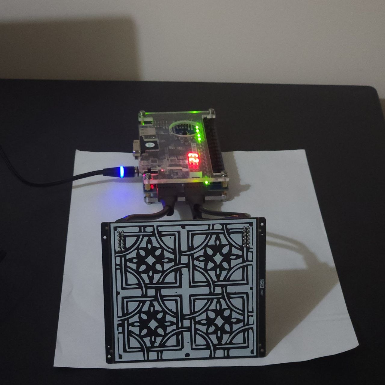 20 kHz source → 30-mic PCB → Pmod → Basys3 → USB → host PC live viewer.
flowchart TD
    MIC["30x SPH0641LU4H\nPDM MEMS mics"] -->|"30x 1-bit PDM"| MM["master_mic.sv\nclock gen + time-multiplexed capture"]
    MM -->|"mic_clk"| MIC
    MM -->|"30x PDM"| CIC["CIC.sv\n4th-order CIC decimation"]
    CIC -->|"30x 18-bit PCM"| GZ["goertzel.sv\nsingle-bin DFT @ target freq"]
    GZ -->|"30x (I,Q) phasors"| BF["beamformer.sv\nCORDIC delay-and-sum (cordic_0 IP)"]
    CTRL["zoom + gain switches"] --> BF
    CTRL --> DD["digit_disp.sv + sevenseg.sv\n7-segment gain readout"]
    BF -->|"1024 pixels, 16-bit"| FB["framebuffer.sv\ndouble-buffered BRAM"]
    FB --> UART["UART.sv\n2 Mbaud"]
    UART --> HOST["live_heatmap.py /\ncamera_overlay.py"]
CAM["webcam"] -->|"camera_overlay.py only"| HOSTmaster_mic.sv) — the 30 microphones are wired as 15 pairs sharing 15 physical pins; even mics are latched on one clock phase, odd mics on the other, so all 30 PDM streams are captured with one mic_clk.CIC.sv) — each mic's 1-bit PDM stream is decimated by a 4th-order CIC filter into signed 18-bit PCM audio.goertzel.sv) — a single-bin Goertzel filter (default target: 20 kHz) runs per microphone, producing the real/imaginary component of that mic's signal at the target frequency.beamformer.sv) — for each of 1024 steering directions (a 32×32 (u,v) grid), a Xilinx CORDIC IP core (cordic_0) rotates every microphone's phasor by the phase delay for that direction; the rotated phasors are summed and the power is written into the corresponding pixel of a double-buffered block-RAM framebuffer. The zoom switch rescales the mic coordinates fed into this calculation, narrowing the steering grid from a 180° field of view down to 60°. The gain switches set how far the accumulated power is right-shifted before being stored, controlling display brightness.UART.sv) — once a full 1024-pixel frame is ready, it's streamed out at 2 Mbaud (0xAA 0x55 sync header, then each pixel as 16-bit little-endian) to a host PC.digit_disp.sv / sevenseg.sv) — the current gain value is continuously multiplexed onto the board's two-digit 7-segment display, so gain can be read without a host PC attached.vga_controller.sv is implemented and was tested driving a live monitor earlier in this project; it's currently unused because the framebuffer only exposes a single read port, which is now assigned to UART for host streaming (not an unfinished module).
Mic positions follow a Fermat/Vogel spiral ("sunflower" pattern) so steering delays are computed from fixed-point (X, Y) coordinates baked into beamformer.sv at synthesis time.
framebuffer.sv ping-pongs between two block RAMs: the beamformer always writes into one while UART reads out the other, swapping only once a full frame is ready and UART has finished the previous one. This avoids ever streaming a half-written frame.CLK_HZ / BAUD = 100,000,000 / 2,000,000 = 50 exactly with an integer UART bit-clock divisor, so there's no baud-rate rounding error accumulating over a frame.MIC_HZ or DECIMATION_FACTOR changes the decimated audio sample rate, which shifts which physical frequency the fixed Goertzel coefficients (COS_w/SIN_w) pick out. This has been verified working down to 10 kHz. That alone does not rescale the beamformer's (X, Y) mic-position constants, though, which are baked in relative to a reference wavelength; retargeting further out requires regenerating a new coordinate set from MATLAB/coordinates.m.Both tools auto-detect the Basys3's UART over USB (FTDI VID:PID 0403:6010), so no port needs to be specified.
live_heatmap.py — a plain live heatmap window. Run it with no arguments.camera_overlay.py — alpha-blends the heatmap over a webcam feed (window 0) instead, with the black→blue→cyan→yellow→red gradient faded in proportionally to signal strength, so quiet regions stay transparent and only real sources light up. A one-pole temporal filter (PERSISTENCE_DECAY) smooths frame-to-frame noise. Hold spacebar to re-center the heatmap on whatever's currently loudest, correcting for the mic array not being perfectly boresighted with the camera.pip install pyserial opencv-python numpy
python3 live_heatmap.py
python3 camera_overlay.py| Path | Contents |
|---|---|
FPGA/ | Vivado 2025.2 project targeting a Digilent Basys3 (xc7a35tcpg236-1). SystemVerilog sources live in acoustic_camera.srcs/sources_1/new/, testbenches in acoustic_camera.srcs/sim_1/new/. |
PCB/ | KiCad project for the 30-mic sensor board (SPH0641LU4H PDM MEMS microphones). |
MATLAB/ | Floating-point beamforming simulation and mic-array coordinate generation used to derive the fixed-point constants in beamformer.sv. |
assets/ | PCB photos/renders and simulated/measured beamformer output, at both FOV settings. |
live_heatmap.py, camera_overlay.py | Live viewers for the UART pixel stream (see above). |
| Module | Role |
|---|---|
acoustic_camera.sv | Top level; wires the mic front end, Goertzel bank, beamformer, framebuffer, UART, and 7-segment display together. |
master_mic.sv | Mic clock generation and time-multiplexed capture of the 30 PDM lines. |
CIC.sv | 4th-order CIC decimation filter, PDM → 18-bit PCM. |
goertzel.sv | Per-mic single-bin DFT at the configured target frequency. |
beamformer.sv | CORDIC-driven phase-domain delay-and-sum beamformer, 32×32 steering grid, switchable 60°/180° FOV and gain. |
framebuffer.sv | Double-buffered (ping-pong) block-RAM frame store; the beamformer writes one buffer while UART reads out the other. |
UART.sv | Streams a completed frame out at 2 Mbaud once frame_ready pulses. |
digit_disp.sv / sevenseg.sv | Multiplexes the current gain value onto the board's 7-segment display. |
vga_controller.sv | Reads the framebuffer and drives standard VGA timing; implemented and tested, currently unused (see above). |
cordic_0 | Vivado-generated CORDIC IP (phase → sin/cos), used by the beamformer. |
| Control | Effect |
|---|---|
gain[4:0] (5 switches) | Sets the right-shift applied to each pixel's accumulated power before storage, controls display brightness/sensitivity. Mirrored on the 7-segment display. |
zoom (switch) | 1 = 60° field of view (zoomed in), 0 = 180° field of view (wide). |
rst (button) | Active-low system reset. |
The 30 PDM lines are time-multiplexed down to 15 physical pins (data[0:14], one pair of mics per pin), split across two Basys3 headers. See FPGA/acoustic_camera.srcs/constrs_1/new/acoustic_camera.xdc for the exact pin-to-signal mapping and PCB/ for which physical mic pair lands on each line:
| Header | Signals |
|---|---|
| Pmod JA | data[8:14], mic_clk |
| Pmod JXADC | data[0:7] |
From FPGA/acoustic_camera.runs/impl_1/ (Vivado 2025.2, xc7a35tcpg236-1, fully placed and routed):
| Resource | Used | Available | Utilization |
|---|---|---|---|
| Slice LUTs | 7,439 | 20,800 | 35.8% |
| Slice Registers | 11,511 | 41,600 | 27.7% |
| Block RAM (RAMB18) | 1 | 50 | 2.0% |
| DSP48E1 | 20 | 90 | 22.2% |
Timing closes at 100 MHz (the system clock constraint) with +0.179 ns worst negative slack, and all user-specified constraints met.
master_mic_tb.sv, beamformer_tb.sv — unit testbenches for the mic front end and beamformer.acoustic_camera_tb.sv — drives a synthetic tone into the full pipeline and dumps the resulting frame to framebuffer.txt.FPGA/sim_image.py converts framebuffer.txt into a viewable PNG for quick visual inspection of simulation results.coordinates.m — generates the Fermat-spiral microphone positions and the fixed-point (X, Y) constants consumed by beamformer.sv.acoustic_camera.m — floating-point simulation of the beamforming algorithm, used to validate steering vectors and visualize expected sound-source power maps (at both 60° and 180° FOV) before committing a design to hardware.Three stages of validation, from the floating-point reference model down to the physical board:
1. MATLAB (floating-point algorithm)
| 60° FOV | 180° FOV | |
|---|---|---|
| Single source | 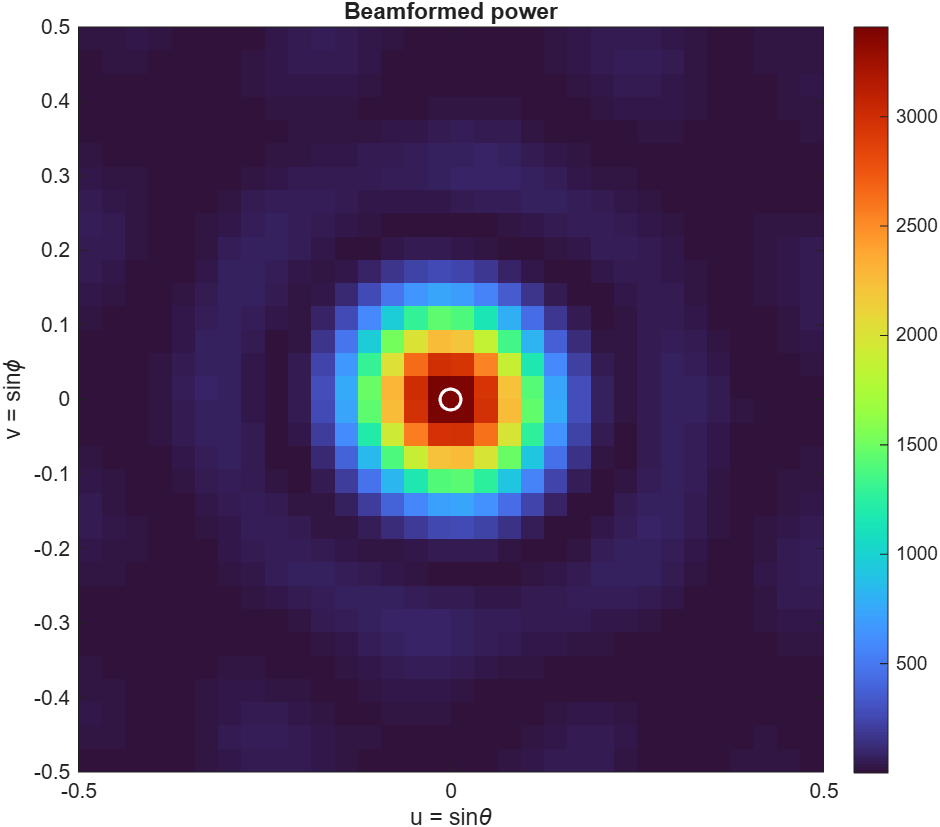 | 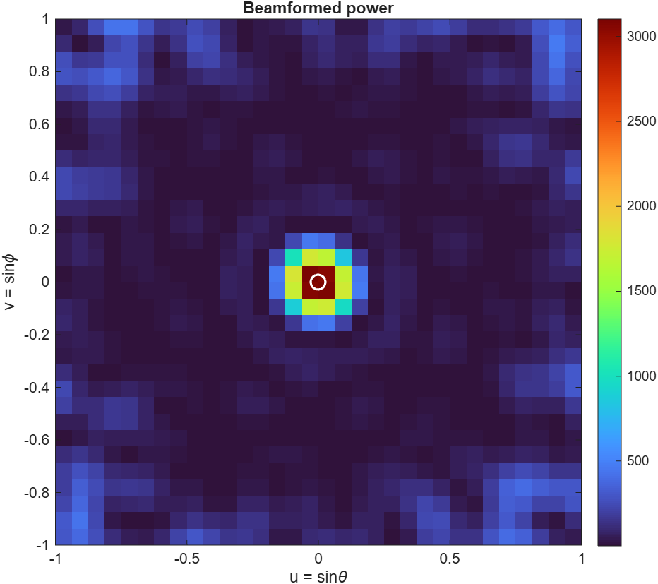 |
| Double source | 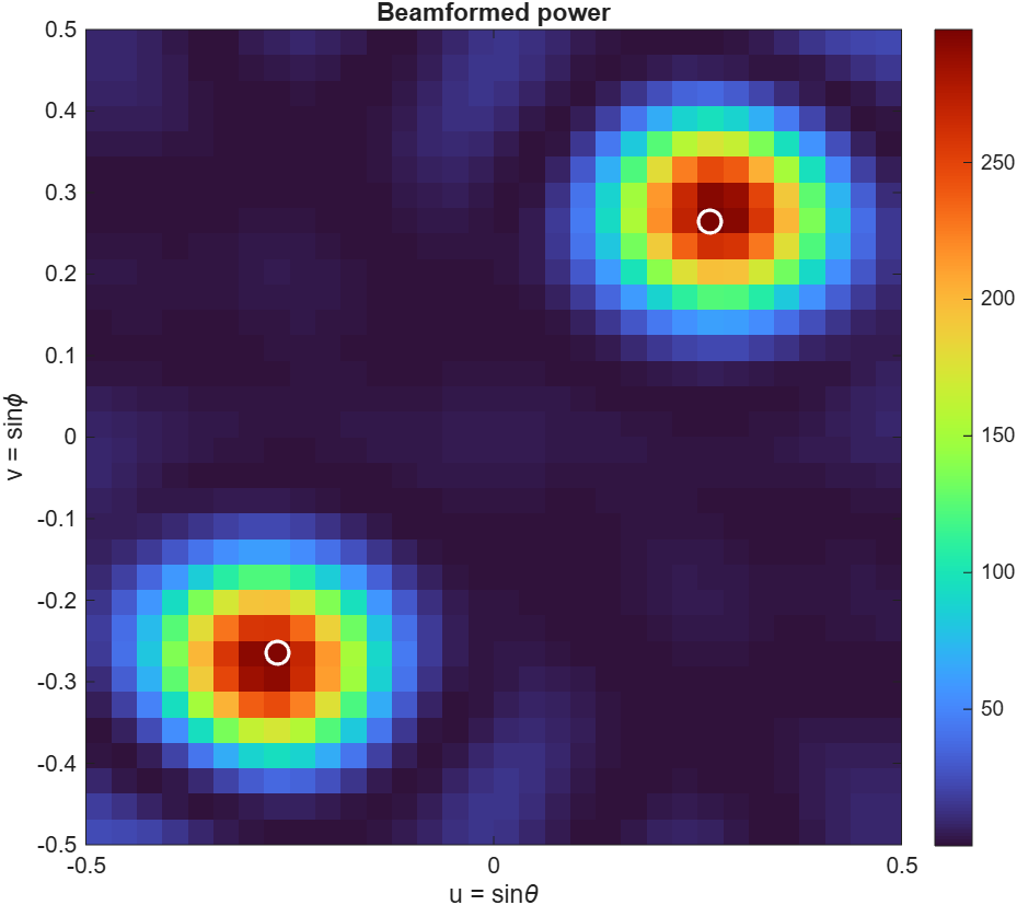 | 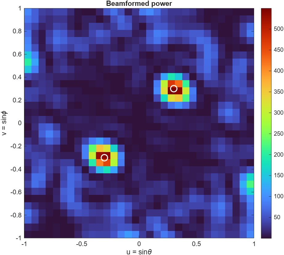 |
Double-source scenes are two equal-level 20 kHz sources, ~30° apart. In the 180° views, the region outside the unit circle (u²+v² > 1) is non-physical. Direction cosines beyond that boundary don't correspond to a real look angle, so ignore any energy shown in the corners.
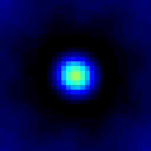
2. Vivado (RTL simulation) — confirms the fixed-point SystemVerilog implementation matches the floating-point reference above:
| 60° FOV | 180° FOV |
|---|---|
 | 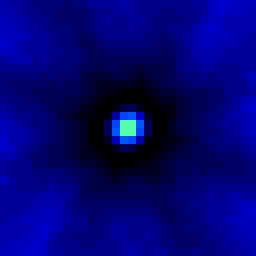 |
3. Hardware (live capture) — via camera_overlay.py, at 60° FOV, same two-equal-level-sources-~30°-apart setup as above:
| Single source | Double source |
|---|---|
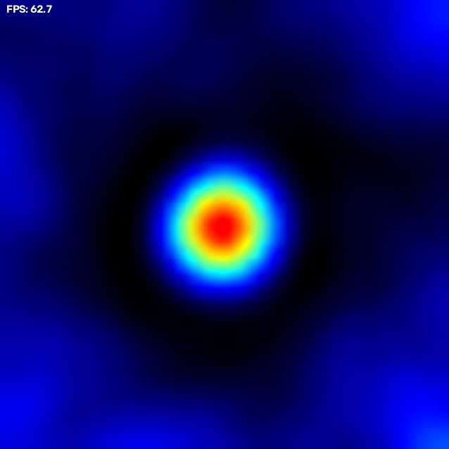 | 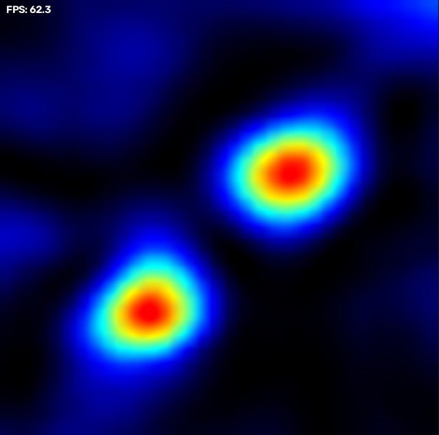 |
| PCB front (model) | PCB back (model) |
|---|---|
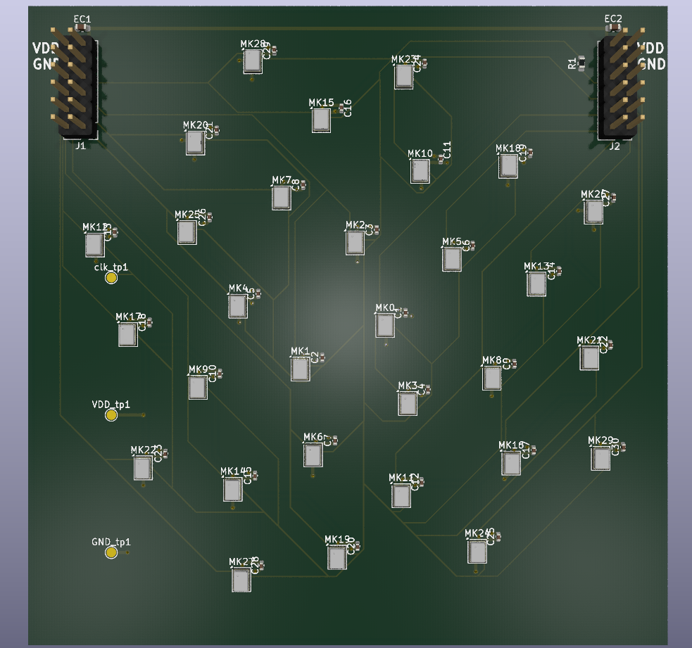 | 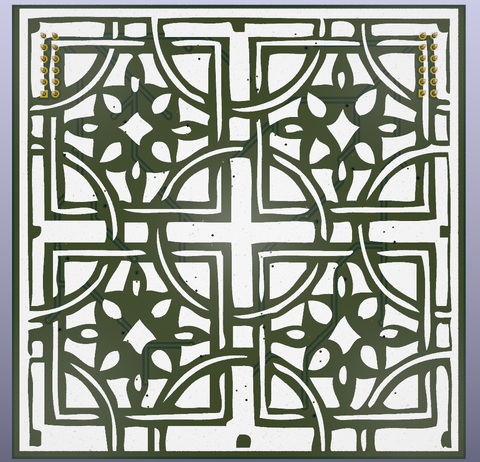 |
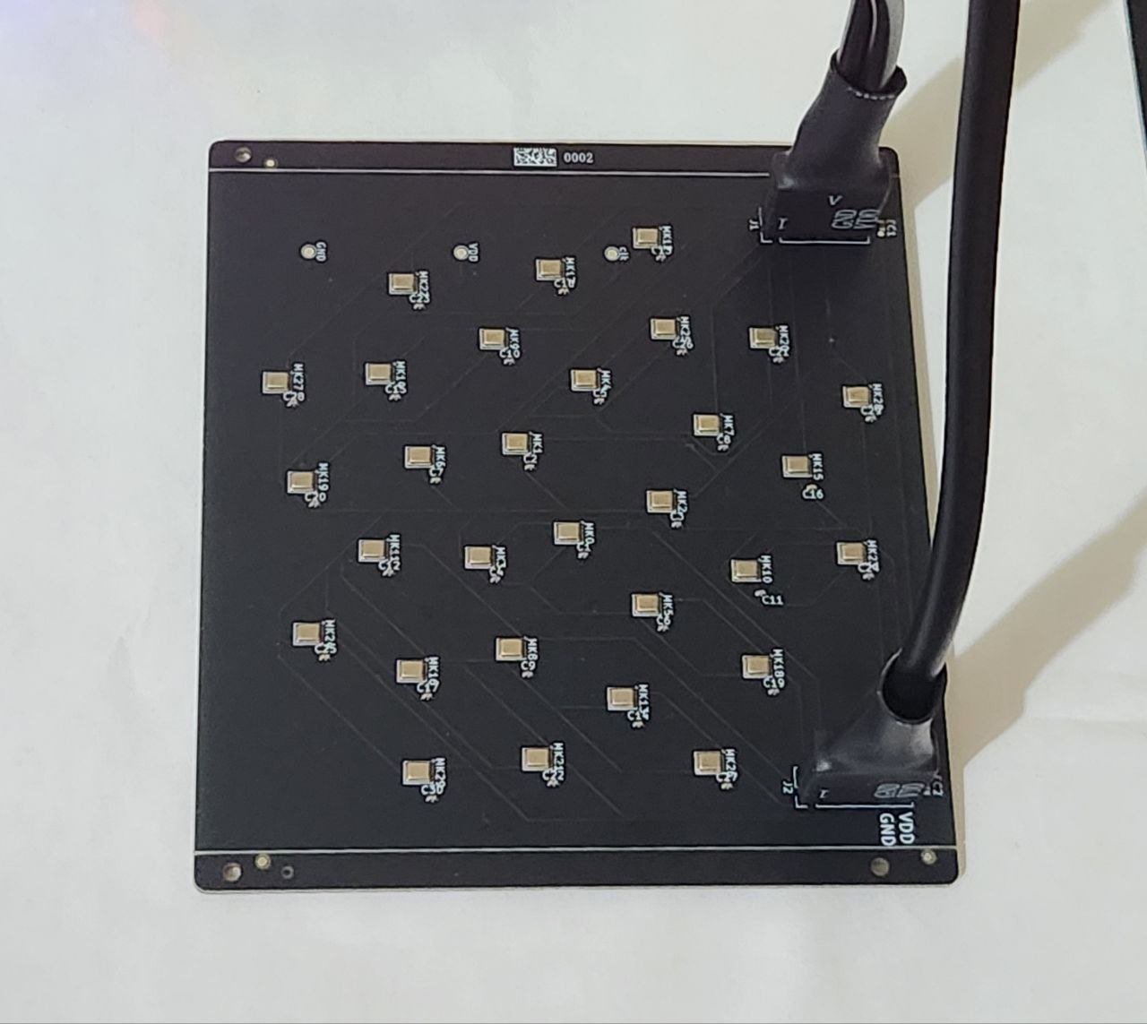
SPH0641LU4H PDM MEMS microphones on a Fermat-spiral array, laid out and placed programmatically via PCB/script.py (KiCad scripting console).FPGA/acoustic_camera.srcs/constrs_1/new/acoustic_camera.xdc).FPGA/acoustic_camera.xpr in Vivado 2025.2 or later (Basys3 board files required); the CORDIC IP core is regenerated automatically from cordic_0.xci.pip install pyserial opencv-python numpy, then run python3 live_heatmap.py or python3 camera_overlay.py (no arguments needed, both auto-detect the board over USB).PCB/acoustic_camera.kicad_pro in KiCad 7+.MATLAB/acoustic_camera.m for the beamforming simulation, or MATLAB/coordinates.m to regenerate the mic array layout constants.End-to-end bring-up on hardware works: populated array → FPGA → UART → live heatmap on a host PC, with switchable FOV/gain and an optional webcam overlay. Remaining work is refinement (calibration, image quality) rather than core functionality.
MIT — see LICENSE.
| Qty | Value | Footprint | References |
|---|---|---|---|
| 30 | 100nF | Capacitor_SMD:C_0402_1005Metric | C1, C2, C10, C11, C12, C13, C14, C15, C16, C17, C18, C19, C20, C21, C22, C23 +14 |
| 30 | SPH0641LU4H-1 | Library:SPH0641LU4H-1 | MK0, MK1, MK2, MK10, MK11, MK12, MK13, MK14, MK15, MK16, MK17, MK18, MK19, MK20, MK21, MK22 +14 |
| 3 | TestPoint | TestPoint:TestPoint_Pad_D1.5mm | clk_tp1, GND_tp1, VDD_tp1 |
| 2 | 1uF | Capacitor_SMD:C_0603_1608Metric | EC1, EC2 |
| 2 | Conn_02x06_Counter_Clockwise | Connector_PinHeader_2.54mm:PinHeader_2x06_P2.54mm_Vertical | J1, J2 |
| 1 | 33 | Resistor_SMD:R_0603_1608Metric | R1 |

meerstern/Sound_Direction_Sensor
This board detects the direction of sound with 4-pdm mems mic using GCC-PHAT algorithm.


0xjmux/iot_leddriver_hw
ESP32-based WS2812B LED Strip Driver PCB, designed for music visualization


Purdue-Northwest-Vibration-Anaylsis/Purdue-Northwest-Vibration-Analysis
Vibration analysis senior design project for purdue northwest.

JackToaster/Wearable-LED-Ring
Tiny LED ring with a microphone for wearable music-reactive lighting

It measures 100 × 100 mm and has 2 copper layers, 1.6 mm thick.
68 parts, built around the SPH0641LU4H-1. The full list of its parts is on this page, with links to each part's symbol and footprint where PCBKit's library has them.
From the mhbbParsa/acoustic_camera repository on GitHub, at the commit this page was made from: the board is PCB/acoustic_camera.kicad_pcb and its schematic PCB/acoustic_camera.kicad_sch. PCBKit opens the board in the browser, with nothing to install.
Its repository publishes it under the MIT licence: you may reuse it on that licence's terms (keep the author's notice, and for a copyleft licence share your changes alike).