4 layers170.2 × 170.2 mm
Nvme Carrier all M2
El-Luhb/nvme-Carrier-for-LattePanda-Mu
nvme Carrier PCB for the LattePanda Mu compute module
400 parts12MIT

 0xjmux/iot_leddriver_hw9
ESP32-based WS2812B LED Strip Driver PCB, designed for music visualization
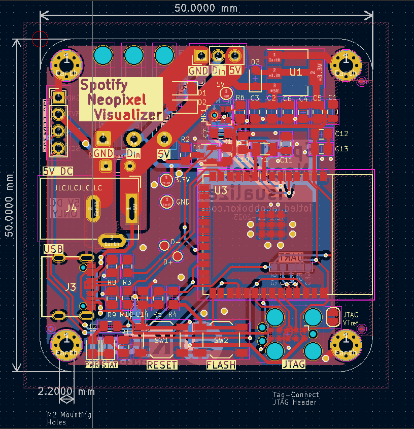
Iot led strip pcb is an open-source printed circuit board by 0xjmux, from the 0xjmux/iot_leddriver_hw repository on GitHub. It is a 4-layer board of 57 × 56 mm with 85 parts on 74 nets, routed with 435 tracks and 74 vias.
It is built around the ESP32-S2-SOLO-N8, SN74AHCT125PWRE4 and AMS1117-3.3, with the PTVSHC3D12VU, 1N4148W and 1N5819WS among its other parts. Its parts include 18 capacitors, 14 resistors, 8 diodes, 6 switches and 5 connectors. It belongs with the lEDs and displays and home automation and IoT boards and the ESP32 boards of this library.


Simple and compact ESP32-based WS2812B LED Strip Driver.
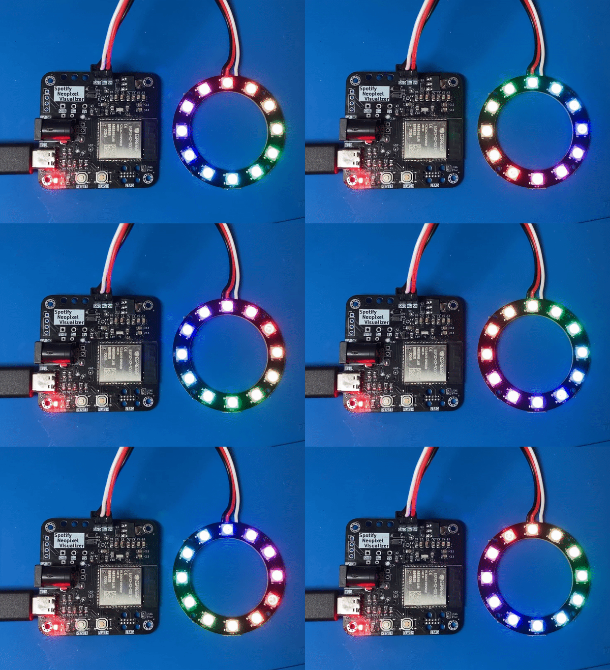
GPIO21.[!WARNING] This was my first real PCB design, and I've improved a lot since I completed it. Take it (especially <=v2.2) with a grain of salt.
ESP32-S2-SOLO (single core, cheaper) or ESP32-S3-WROOM (dual core).D1&D2, PN SMF5V0A) to 12V diodes (like SMF12As)
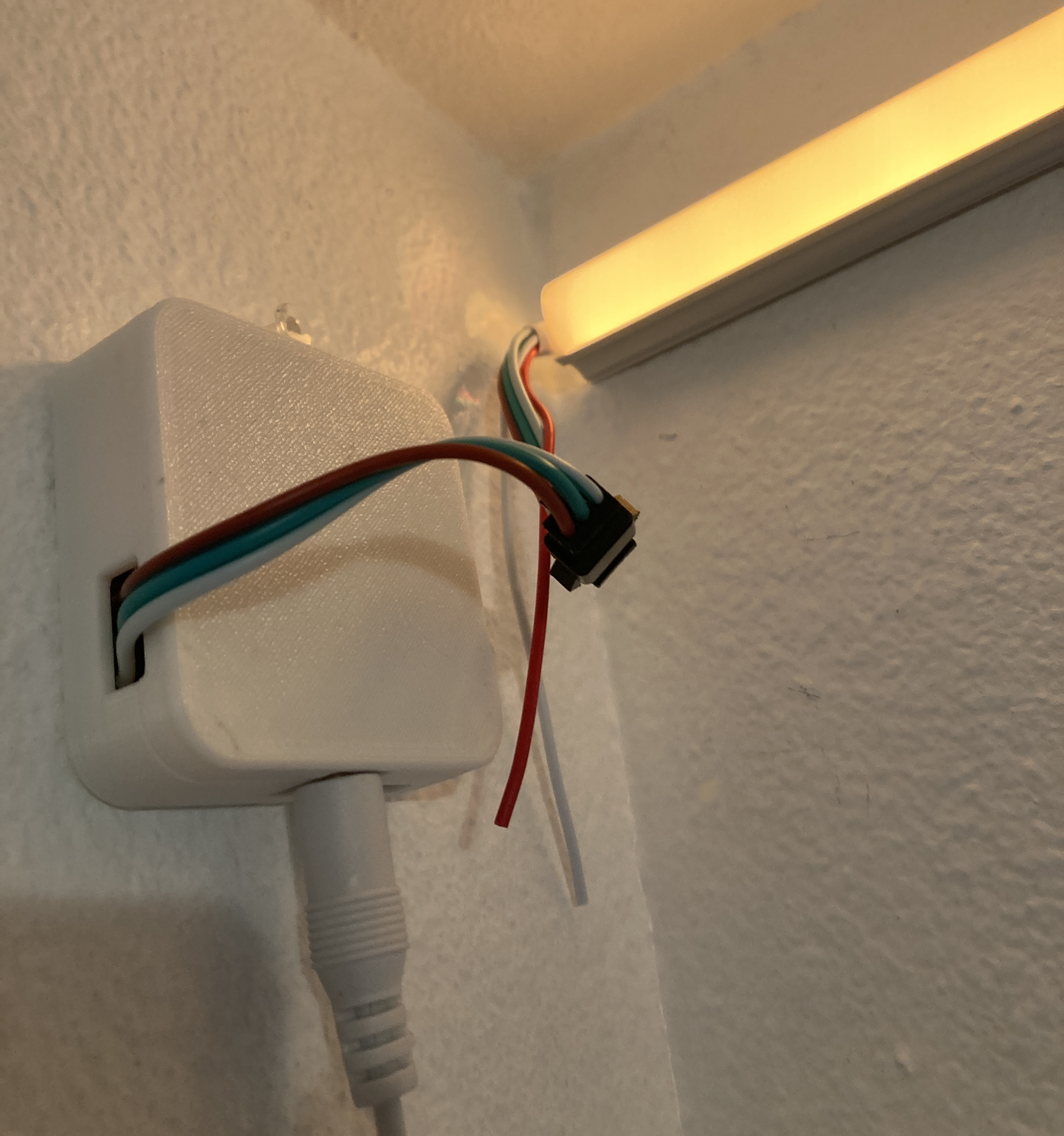
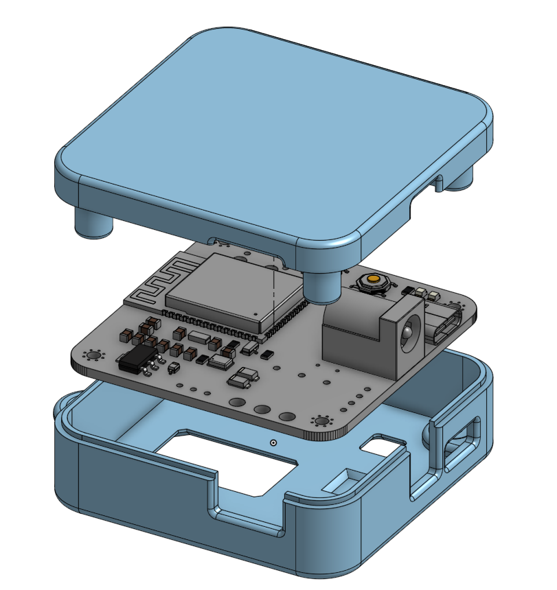
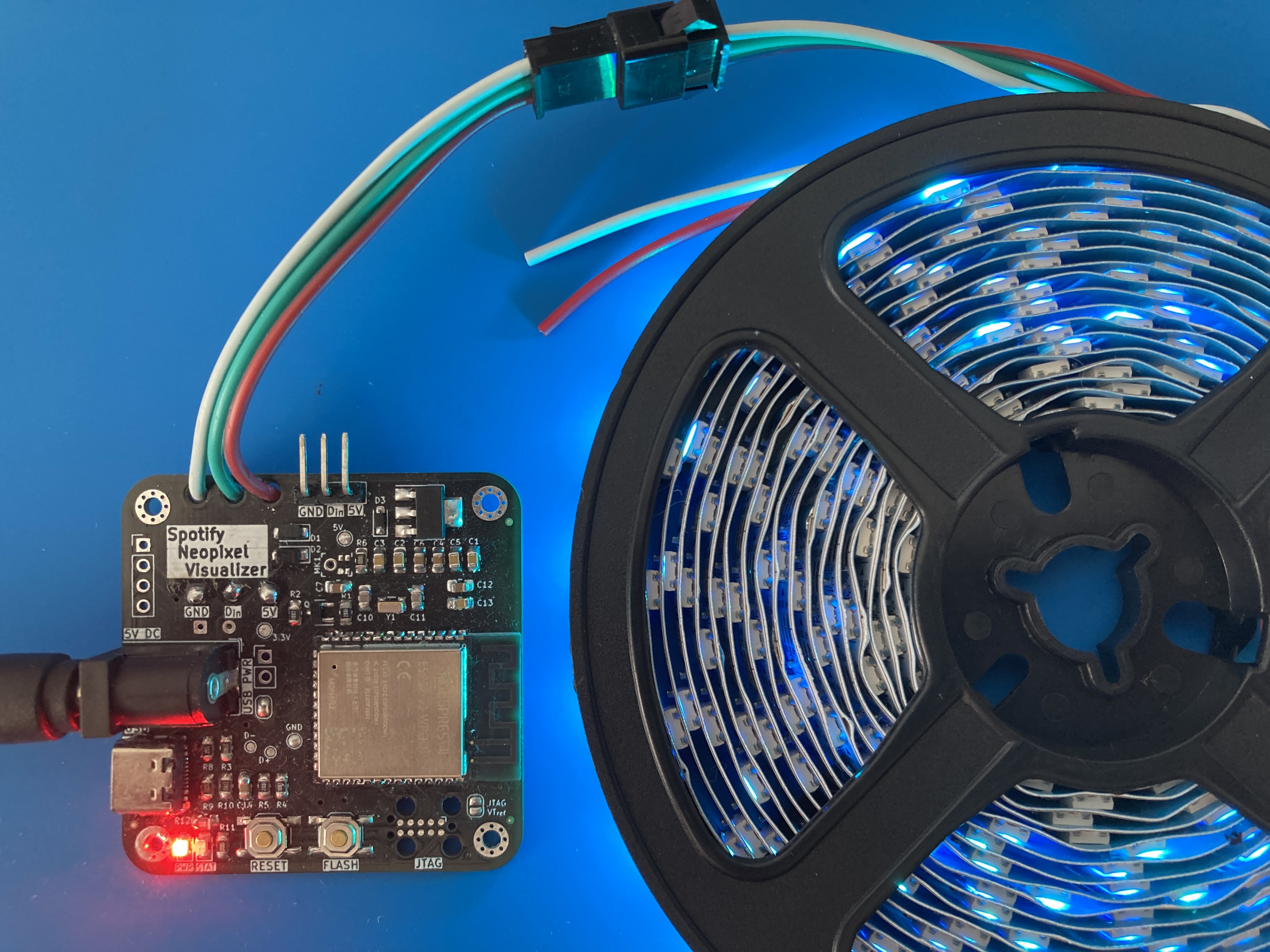
v2.1 showing LED strip standard JST connector connected to 5M WS2812B strip
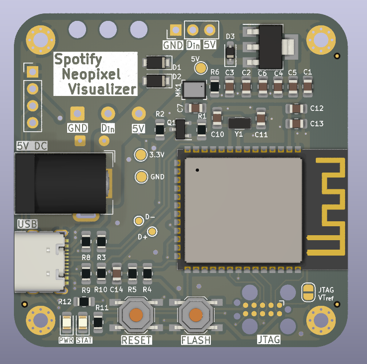
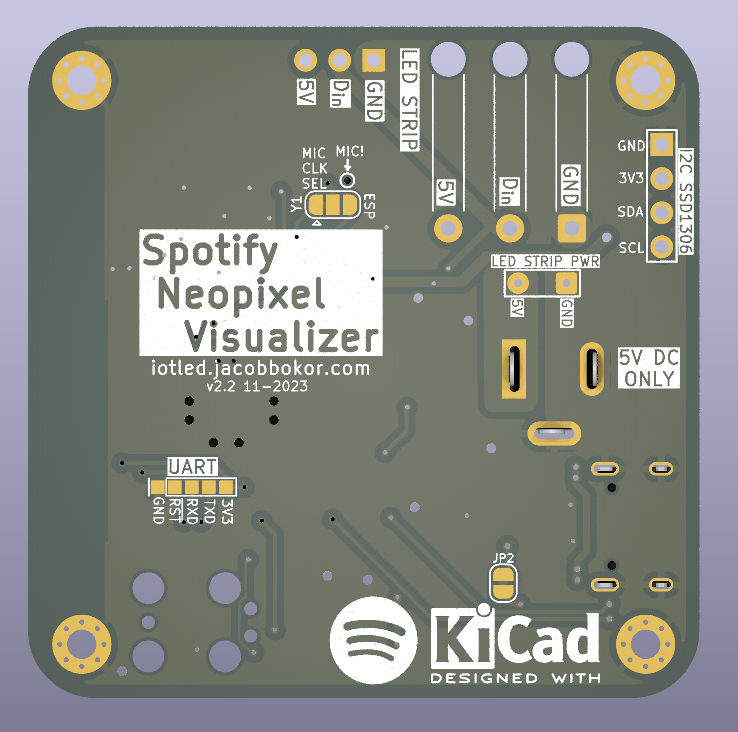
ESP32-S2-MINI, wasn't hand assemble-able; so it's been replaced with an ESP32-S2-SOLO.SPH0641LM4H-1) added in case live sound reactivity is desired later on.
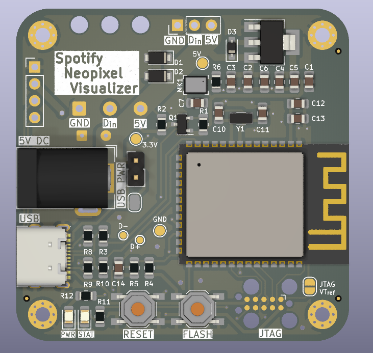
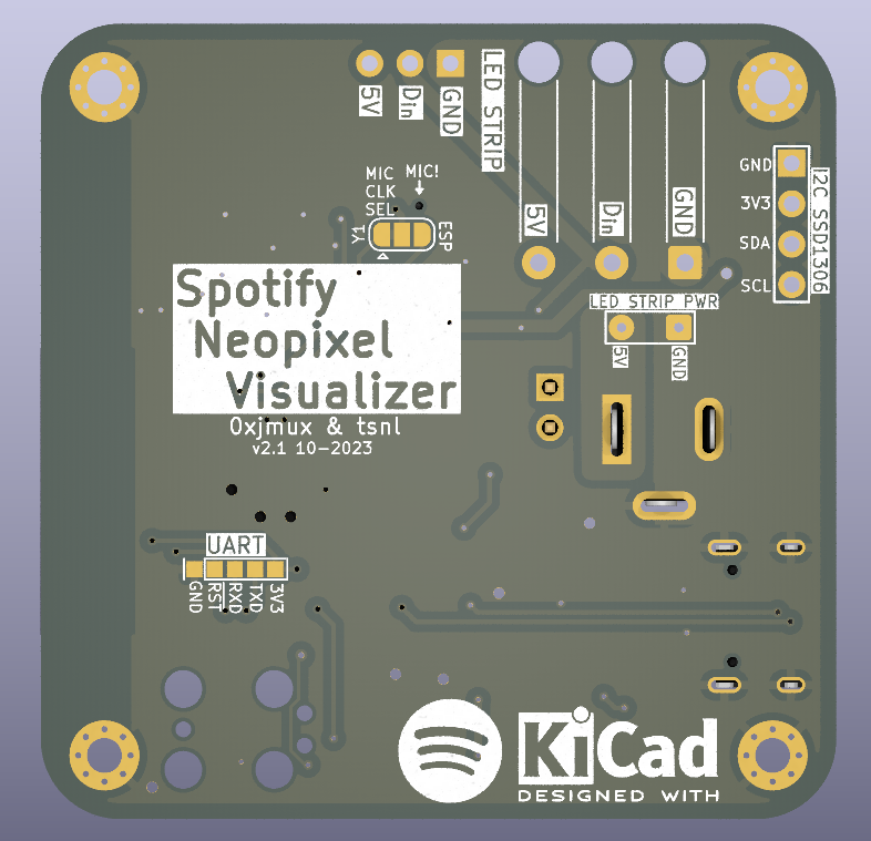
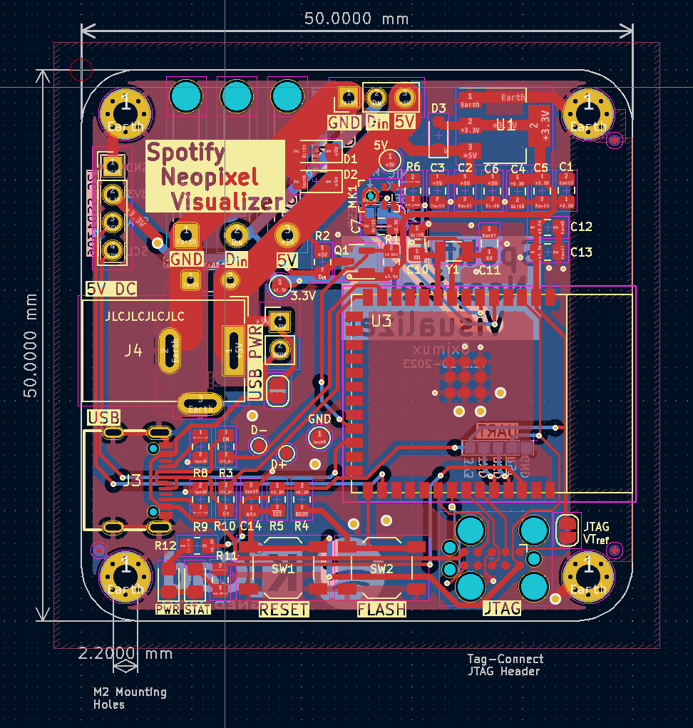
ESP32-S2-MINI-2-N4 for better compute capability, completely redesigned solely around the WS2812B.
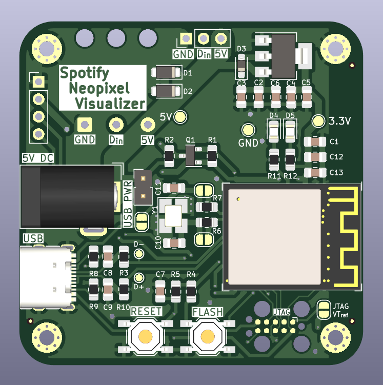
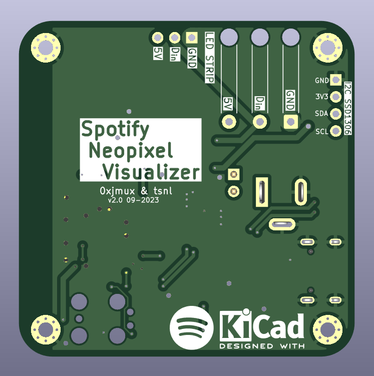
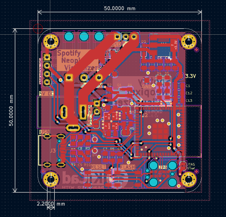
UMW30N06 Mosfets and 2 of the MCP1416 mosfet drivers are not needed. Additionally, if the board will only be run in one mode then the unused 2.1mm jack does not need to be installed.
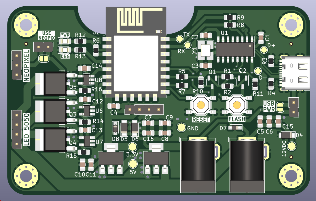
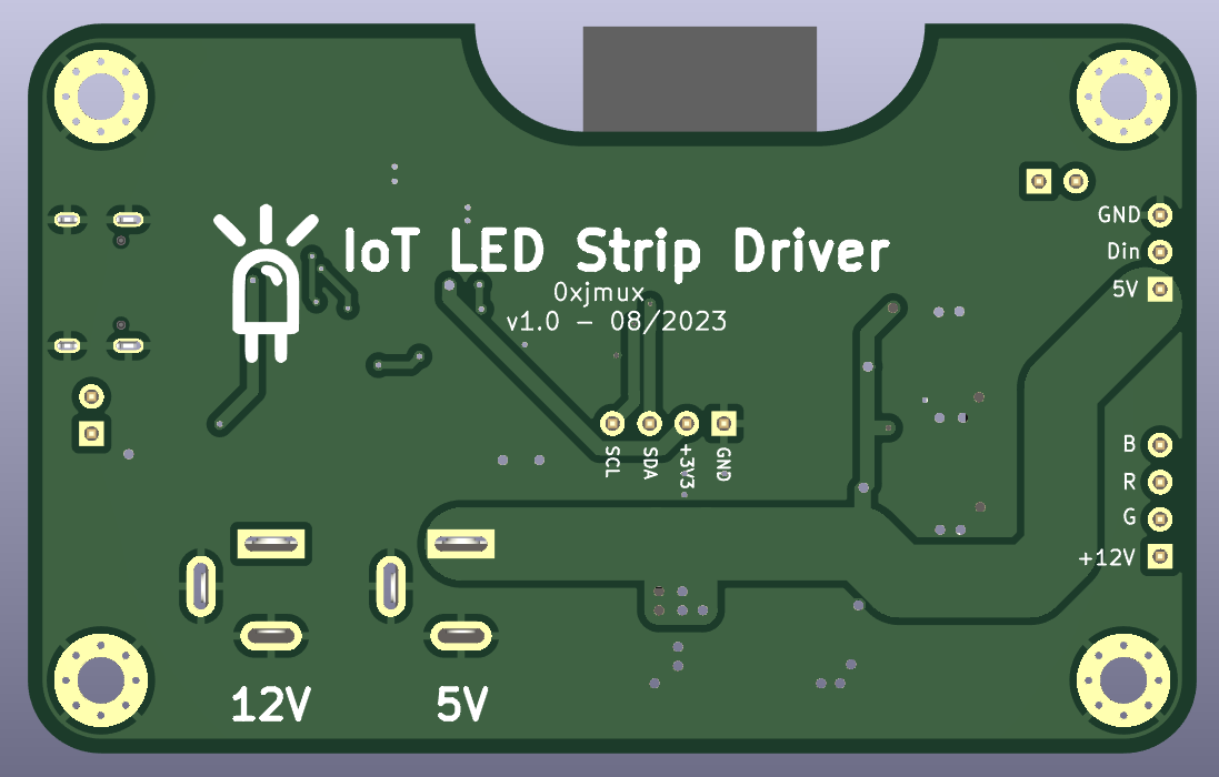
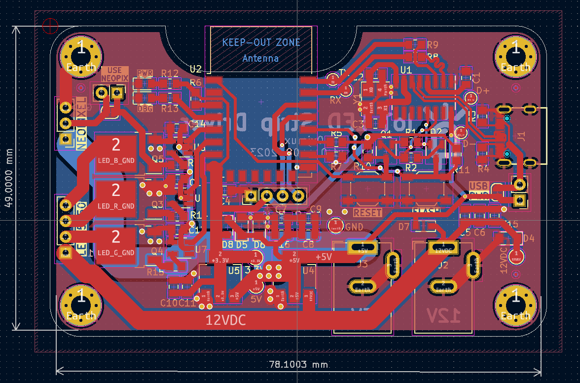
| Qty | Value | Footprint | References |
|---|---|---|---|
| 9 | 100nF | Capacitor_SMD:C_0805_2012Metric_Pad1.18x1.45mm_HandSolder | C4, C6, C7, C9, C10, C11, C12, C14, C18 |
| 9 | 10uF | Capacitor_SMD:C_0805_2012Metric_Pad1.18x1.45mm_HandSolder | C1, C2, C3, C5, C8, C13, C15, C16, C17 |
| 3 | 10k | Resistor_SMD:R_0805_2012Metric_Pad1.20x1.40mm_HandSolder | R1, R4, R5 |
| 3 | Fiducial | Fiducial:Fiducial_0.5mm_Mask1mm | FID1, FID2, FID3 |
| 3 | MountingHole_Pad | MountingHole:MountingHole_2.2mm_M2_Pad_Via | H1, H2, H3 |
| 2 | 1k | Resistor_SMD:R_0805_2012Metric_Pad1.20x1.40mm_HandSolder | R12, R14 |
| 2 | 220R | Resistor_SMD:R_0805_2012Metric_Pad1.20x1.40mm_HandSolder | R16, R18 |
| 2 | 27R | Resistor_SMD:R_0805_2012Metric_Pad1.20x1.40mm_HandSolder | R3, R10 |
| 2 | 33R | Resistor_SMD:R_0805_2012Metric_Pad1.20x1.40mm_HandSolder | R7, R17 |
| 2 | 5.1k | Resistor_SMD:R_0805_2012Metric_Pad1.20x1.40mm_HandSolder | R8, R9 |
| 2 | PTVSHC3D12VU | Diode_SMD:D_SOD-323_HandSoldering | D7, D8 |
| 2 | SMF5V0A | Diode_SMD:D_SMF | D1, D2 |
| 2 | SW_SPDT | Button_Switch_SMD:SW_SPDT_PCM12 | SW3, SW4 |
| 2 | Screw_Terminal_01x03 | TerminalBlock:TerminalBlock_bornier-3_P5.08mm | J1, J2 |
| 2 | SolderJumper_3_Open | Jumper:SolderJumper-3_P1.3mm_Open_Pad1.0x1.5mm | JP5, JP6 |
| 1 | 100 | Resistor_SMD:R_0805_2012Metric_Pad1.20x1.40mm_HandSolder | R6 |
| 1 | 12V TVS DISCON. | Jumper:SolderJumper-2_P1.3mm_Open_RoundedPad1.0x1.5mm | JP8 |
| 1 | 12V_5V_SWT | Button_Switch_SMD:SW_SPDT_PCM12 | SW5 |
| 1 | 1N4148W | Diode_SMD:D_SOD-123 | D6 |
| 1 | 1N5819WS | Diode_SMD:D_SOD-323_HandSoldering | D3 |
| 1 | 3.3V | TestPoint:TestPoint_Pad_D1.5mm | TP2 |
| 1 | 5V | TestPoint:TestPoint_Pad_D1.5mm | TP10 |
| 1 | 5V TVS DISCON. | Jumper:SolderJumper-2_P1.3mm_Open_RoundedPad1.0x1.5mm | JP4 |
| 1 | AMS1117-3.3 | Package_TO_SOT_SMD:SOT-223-3_TabPin2 | U1 |
| 1 | AO3400A | Package_TO_SOT_SMD:SOT-23_Handsoldering | Q1 |
| 1 | Barrel_Jack_Switch_Pin3Ring | Connector_BarrelJack:BarrelJack_Wuerth_6941xx301002 | J4 |
| 1 | D+ | TestPoint:TestPoint_Pad_D1.5mm | TP4 |
| 1 | D- | TestPoint:TestPoint_Pad_D1.5mm | TP5 |
| 1 | ESP32-S2-SOLO | PCM_Espressif:ESP32-S2-SOLO | U3 |
| 1 | FLASH | Button_Switch_SMD:SW_SPST_TL3342 | SW2 |
| 1 | Fuse Holder | jmux-footprints:FUSE-TH_XF-505P | F2 |
| 1 | GND | TestPoint:TestPoint_Pad_D1.5mm | TP3 |
| 1 | GT-USB-7010ASV | jmux-footprints:USB-C-GT7010_FIXED | J3 |
| 1 | IO10 | TestPoint:TestPoint_Pad_D1.5mm | TP9 |
| 1 | IO9 | TestPoint:TestPoint_Pad_D1.5mm | TP8 |
| 1 | LL_in | TestPoint:TestPoint_Pad_D1.0mm | TP11 |
| 1 | LL_out | TestPoint:TestPoint_Pad_D1.0mm | TP13 |
| 1 | LL_~{OE} | TestPoint:TestPoint_Pad_D1.0mm | TP12 |
| 1 | MIC SEL | Jumper:SolderJumper-3_P1.3mm_Bridged12_RoundedPad1.0x1.5mm | JP7 |
| 1 | PWR | LED_SMD:LED_0805_2012Metric_Pad1.15x1.40mm_HandSolder | D5 |
| 1 | PWR_HEADER | Connector_Wire:SolderWire-0.5sqmm_1x02_P4.6mm_D0.9mm_OD2.1mm | J7 |
| 1 | PWR_LED_BRIDGE | Jumper:SolderJumper-2_P1.3mm_Bridged_RoundedPad1.0x1.5mm | JP2 |
| 1 | RESET | Button_Switch_SMD:SW_SPST_TL3342 | SW1 |
| 1 | RX | TestPoint:TestPoint_Pad_D1.5mm | TP7 |
| 1 | SANYOU_SRD_Form_C | Relay_THT:Relay_SPDT_SANYOU_SRD_Series_Form_C | K2 |
| 1 | SN74AHCT125PWR | Package_SO:TSSOP-14_4.4x5mm_P0.65mm | U4 |
| 1 | SPH0641LU4H-1 | Sensor_Audio:Knowles_LGA-5_3.5x2.65mm | MK1 |
| 1 | STAT | LED_SMD:LED_0805_2012Metric_Pad1.15x1.40mm_HandSolder | D4 |
| 1 | TAR5S50 | projectlib:SSOP-5_L2.9-W1.6-P0.95-LS2.8-TL | U2 |
| 1 | TX | TestPoint:TestPoint_Pad_D1.5mm | TP6 |
| 1 | USB-VCC | Jumper:SolderJumper-2_P1.3mm_Open_RoundedPad1.0x1.5mm | JP3 |
| 1 | USB-VDD | TestPoint:TestPoint_2Pads_Pitch2.54mm_Drill0.8mm | JP1 |
| 1 | Vdd | TestPoint:TestPoint_Pad_D1.5mm | TP1 |
El-Luhb/nvme-Carrier-for-LattePanda-Mu
nvme Carrier PCB for the LattePanda Mu compute module

Team-Micras/MicrasPCB
Micras micromouse PCBs as code: Zener circuits, KiCad layouts, CI checks and a design portal


moclei/motion-play
Motion sensing project for fast moving objects moving through a plane. With directionality.

hackclub/OnBoard
💡 Join 1,000 teenagers and make your first PCB with a $100 grant!


It measures 57 × 56 mm and has 4 copper layers, 1.6 mm thick.
85 parts, built around the ESP32-S2-SOLO-N8, SN74AHCT125PWRE4, AMS1117-3.3 and PTVSHC3D12VU. The full list of its parts is on this page, with links to each part's symbol and footprint where PCBKit's library has them.
From the 0xjmux/iot_leddriver_hw repository on GitHub, at the commit this page was made from: the board is PCB/iot_led_strip_pcb.kicad_pcb and its schematic PCB/Power_and_board.kicad_sch. PCBKit opens the board in the browser, with nothing to install.
Its repository states no licence, so its author keeps all rights: ask 0xjmux before reusing the design.