2 layers50 × 66 mm
 metaquantus/camel
Camel Dual HX711 Weigh Scales Board
Camel is an open-source printed circuit board by metaquantus, from the metaquantus/camel repository on GitHub, published under the MIT licence. It is a 4-layer board of 55 × 28 mm with 66 parts on 49 nets, routed with 314 tracks and 118 vias.
It is built around the STM32L071KBU6, HX712 and MCP1700T-3302E/TT(MS), with the RCLAMP0521P-N among its other parts. Its parts include 17 capacitors, 15 diodes, 11 resistors, 7 connectors and 4 ICs. It belongs with the STM32 boards of this library.


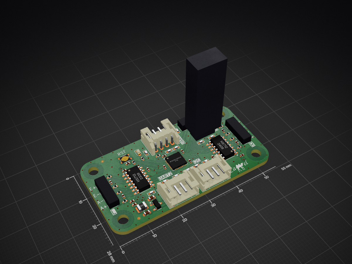
Camel is a board with Dual HX712 Weigh Scales ADCs controlled by a low power STM32L010F4 or STM32L031F6 MCU providing an I2C slave interface. Power is provided by an I2C Adafruit STEMMA compatible 4-pin JST PH (2mm pitch) connector. This board will work with power from 3.3V to 5V, but it's better if VCC > 4V.
It was intended to support the integrated scales mod for the Gaggia Classic Pro espresso machine provided by the Gaggiuino project. But instead of the main MCU driving the HX712s directly, sensor reading and decoding is offloaded to this board's MCU and a simple I2C interface is used instead to connect to the host MCU. This reduces the number of wires required, frees some pins in the host MCU and saves some clock cycles.
STEMMA Pinouts:
1 Green for SCL
2 White for SDA
3 Red for VCC+
4 Black for GND
The MCU drives the 2 HX712 ADCs, reads and decodes the conversions and provides the raw data to the host via I2C. The HX712s allow programmatic configuration of the sampling rate (10Hz or 40Hz), the amplifier's gain factor (128 or 256) and whether to put the HX712s into power down mode consuming less than 1uA. The device can also store configuration and calibration points in the MCU's EEPROM. Up to 4 calibration points are supported. The host is in charge of providing additional functions like scaling to weight units, tare and calibration. It may be possible to offload scaling to the MCU, if using STM32L031F6 as it has more memory. I2C doesn't support slave initiated transfers so the host MCU must poll the device periodically to read the data. There will be roughly one new sensor reading available of both load cells every 100ms if 10Hz sampling rate is used. The internal oscillator is used in both the HX712 ADCs and the MCU so sampling rates are not very precise. Using the lower sampling rate has lower conversion noise. The HX712 is a 24-bit ADC and data is provided in 2's complement format. Readings could be negative depending on how the load cell is mechanically setup, bending one way of the other. For example, in some of the integrated scales mod assembles, one cell gives positive values and the other negative. To get the total weight reading, the absolute values of both cells should be added.
According to STM32CubeIDE, the MCU should consume about 5mA and the HX712s about 1mA each.
If using only one of the HX712s, it's possible power down the other, saving 1mA. This can be configured from the host.
Programming is done via a Serial Wire Debug (SWD) connector. Both a Tag-Connect TC2030-NL and a 4-pin 2.54mm pitch header are provided for SWD.
A USART connector is provided but the STM32L010F4 has only 16Kb flash/2Kb RAM and adding code support exceeds code size limit. Some reporting was tried but code size was very tight. This was intended for monitor and debugging during development, so it's not essential. Maybe with the STM32L031F6 with 32KB flash/8KB RAM more monitoring and functions like standalone calibration can be added.
ESD protection diodes were added to the interface connectors.
2.54mm pitch header THT pads are used for the load cell connectors, but normally the load cells wires should be soldered directly to the pads instead of using headers or other connector.
The variable FAB_ON_PLACEHOLDER should be set to JLCJLCJLCJLC, WayWayWay or whatever string is specified by the Fab to position the order number. Or removed altogether if so desired. Sometimes a fee is incurred if removed.
| Qty | Value | Footprint | References |
|---|---|---|---|
| 14 | RCLAMP0521P-N | camel:X1-DFN1006-2_L1.0-W0.6-BI | D1, D2, D3, D4, D6, D7, D8, D9, D10, D11, D12, D13, D14, D15 |
| 13 | 100n | Capacitor_SMD:C_0402_1005Metric | C1, C2, C7, C8, C9, C10, C11, C12, C13, C14, C15, C16, C17 |
| 4 | 100R | Resistor_SMD:R_0402_1005Metric | R1, R2, R7, R8 |
| 4 | 200R | Resistor_SMD:R_0402_1005Metric | R3, R4, R9, R10 |
| 4 | MountingHole | MountingHole:MountingHole_3.2mm_M3 | H1, H2, H3, H4 |
| 3 | Conn_01x04 | camel:Pad_1x04_P2.54mm | J1, J2, J5 |
| 3 | Fiducial | Fiducial:Fiducial_0.5mm_Mask1mm | FID1, FID2, FID3 |
| 2 | 10K | Resistor_SMD:R_0402_1005Metric | R6, R11 |
| 2 | 10u | Capacitor_SMD:C_0603_1608Metric | C5, C6 |
| 2 | HX712 | Package_SO:SOIC-14_3.9x8.7mm_P1.27mm | U2, U4 |
| 1 | 10n | Capacitor_SMD:C_0402_1005Metric | C3 |
| 1 | 1u | Capacitor_SMD:C_0402_1005Metric | C4 |
| 1 | 2K2 | Resistor_SMD:R_0402_1005Metric | R5 |
| 1 | 39n | Inductor_SMD:L_1008_2520Metric | L1 |
| 1 | I2C STEMMA | Connector_JST:JST_PH_S4B-PH-K_1x04_P2.00mm_Horizontal | J6 |
| 1 | LOGO | camel:camel_logo_7 | G3 |
| 1 | LOGO | camel:camel_logo_30 | G*** |
| 1 | MCP1700T-3302E/TT | Package_TO_SOT_SMD:SOT-23 | U1 |
| 1 | QR | camel:camel_qrcode_5x5 | QR1 |
| 1 | RED | LED_SMD:LED_0603_1608Metric | D5 |
| 1 | RESET | camel:SW-SMD_4P-L3.0-W2.6-P1.80-LS3.5 | SW1 |
| 1 | STM32L071KBU6 | Package_DFN_QFN:QFN-32-1EP_5x5mm_P0.5mm_EP3.45x3.45mm | U3 |
| 1 | TC2030-NL | Connector:Tag-Connect_TC2030-IDC-NL_2x03_P1.27mm_Vertical | J3 |
| 1 | UART1 | camel:JST_PH_S4B-PH-K_1x04_P2.00mm_Horizontal_TC-2030-IDC-NL_2x03_P1.27mm_Vertical | J4 |
| 1 | UART2 | Connector_JST:JST_PH_S4B-PH-K_1x04_P2.00mm_Horizontal | J7 |
It measures 55 × 28 mm and has 4 copper layers, 1.6 mm thick.
66 parts, built around the STM32L071KBU6, HX712, MCP1700T-3302E/TT(MS) and RCLAMP0521P-N. The full list of its parts is on this page, with links to each part's symbol and footprint where PCBKit's library has them.
From the metaquantus/camel repository on GitHub, at the commit this page was made from: the board is pcb/camel.kicad_pcb and its schematic pcb/camel.kicad_sch. PCBKit opens the board in the browser, with nothing to install.
Its repository publishes it under the MIT licence: you may reuse it on that licence's terms (keep the author's notice, and for a copyleft licence share your changes alike).

MartinVerges/womolin-waterlevel
DIY project to build a smart fuel sensor for RVs or in other projects. It is based on air pressure and is able to measure fresh water as well as grey and black water levels with high precision.


harry10086/InkWord_ESP32
An ESP32 and E-paper based low-power English vocabulary learning device.一个基于 ESP32 和墨水屏的低功耗英语单词学习设备。


pierrechevalier83/ferris
A low profile split keyboard designed to satisfy one single use case elegantly