4 layers108 × 81 mm
Foc dev board
dganin-hw/bldc-foc
Контроллер бесколлекторного мотора с FOC на STM32G431: своя силовая плата, плата энкодера AS5047P, печатный стенд и прошивка на C
149 parts

 metallarox/eload-60v
Electronic load 60V
Eload 4ch is an open-source printed circuit board by metallarox, from the metallarox/eload-60v repository on GitHub, published under the CERN-OHL-S-2.0 licence. It is a 2-layer board of 170 × 125 mm with 143 parts on 84 nets, routed with 1,248 tracks and 183 vias.
It is built around the OPA2196ID, AP63205WU and DAC8565IAPW, with the L78L05ACD13TR-MS, LM393DRG and PCF8574T/3 among its other parts. Its parts include 55 resistors, 43 capacitors, 12 ICs, 9 connectors and 7 transistors. It belongs with the power boards and the ESP8266 boards of this library.


An open-hardware DC electronic load with four independent constant-current channels, 20-bit measurement on every channel, a hardware fail-safe that does not depend on firmware, and WiFi control through a plug-in ESP8266 module.
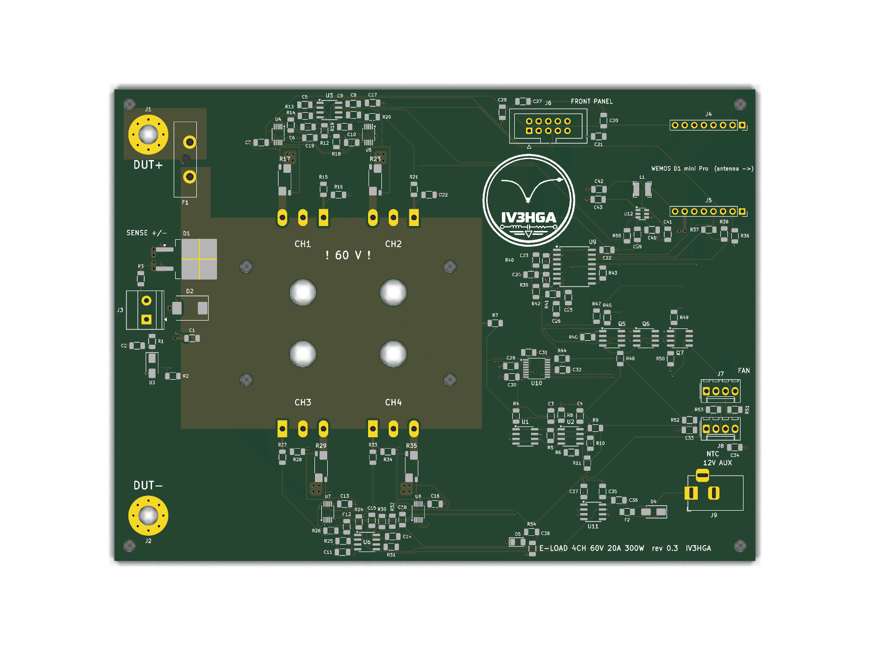
Status: rev 0.3 — design complete, not yet built or bench-tested. ERC and DRC (with schematic parity) are clean, and the control loop and thermal budget have been analysed numerically. Treat it as a reviewed design, not a proven product. Bench reports, issues and pull requests are very welcome.
| Parameter | Value |
|---|---|
| Input voltage | 0 – 60 V (hardware OVP trips at 64.7 V) |
| Current | 4 channels × 0 – 5 A = 20 A |
| Power | 4 × 75 W = 300 W continuous (power-limited above 15 V) |
| Mode | Constant current per channel; CP / CR in firmware |
| Setpoint | DAC8565, 16 bit → 76 µA per LSB per channel |
| Measurement | INA228 per channel: 20-bit, Kelvin shunt, remote voltage sense |
| Control | WiFi, Wemos LOLIN D1 mini Pro (ESP8266) on sockets; front panel with I²C OLED, encoder and OUTPUT button |
| Protection | OVP, OTP, per-channel over-current/over-power ALERT, reverse-polarity crowbar, 25 A fuse |
| Loop | Phase margin ≈ 80°, closed-loop bandwidth 6 – 15 kHz (model) |
| PCB | 170 × 125 mm, 2 layers, 2 oz copper, KiCad 10 |
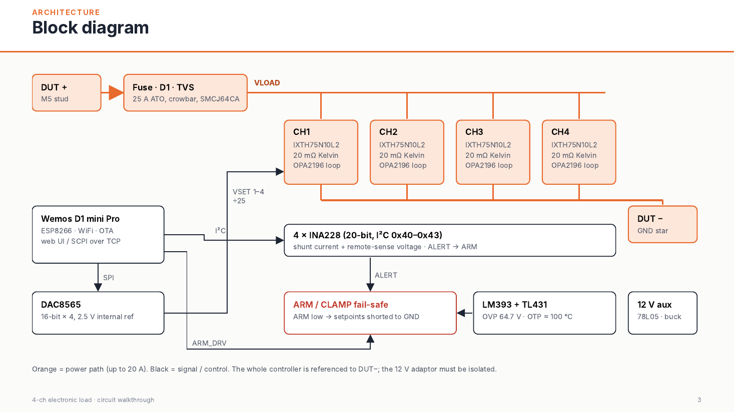
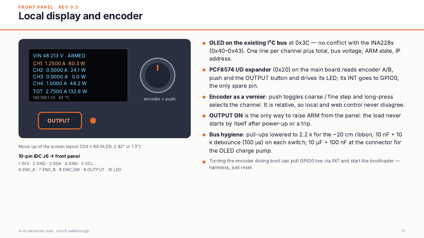
The full walkthrough, including SOA, thermal budget and loop-stability analysis, is in docs/Electronic_Load_Circuit_Walkthrough.pdf (20 slides).
| SOA | Loop gain |
|---|---|
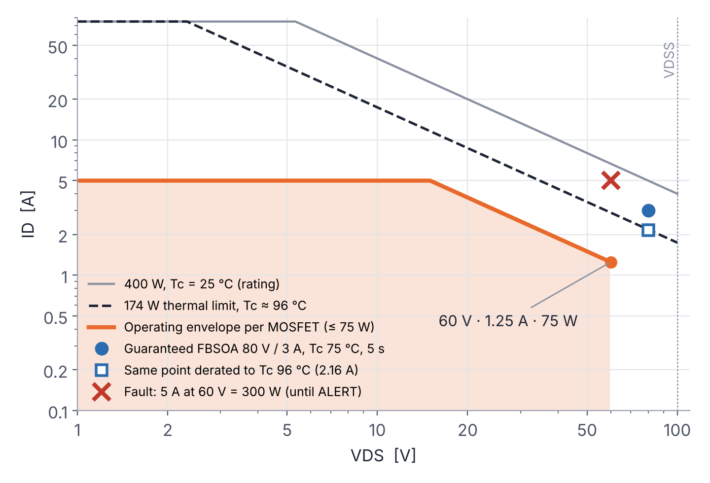 | 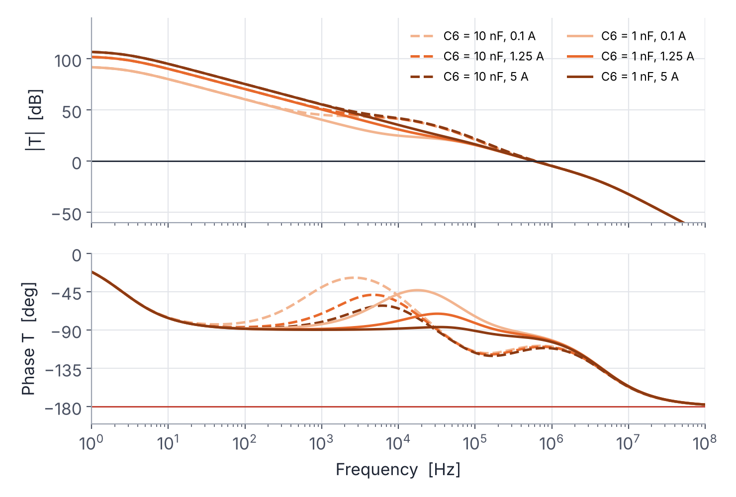 |
The model and scripts are in analysis/. Op-amp second pole and output resistance, the cooler's thermal resistance and the pad are assumptions, listed in the slides.
hardware/
  kicad/          KiCad 10 project (eload_4ch.kicad_pro), custom symbols, DRC rules
  fabrication/    Gerbers + drill (zip) and pick-and-place positions, rev 0.3
  bom/            BOM from KiCad (CSV) and priced BOM with sources (XLSX)
docs/
  Electronic_Load_Circuit_Walkthrough.pdf   slide deck (English)
  assembly/       interactive HTML BOM, top/bottom assembly drawings
  eload_4ch_schematic.pdf, eload_4ch_pcb.pdf
  images/, reports/ (ERC / DRC)
firmware/         ESP8266 firmware (Arduino core), web page, unit tests, mock server, prebuilt bin
analysis/         loop model (sympy/scipy), large-signal sim, SOA/thermal plots
tools/generator/  Python scripts that generated the schematic and placed/routed the PCB
Schematic, PCB and the KiCad BOM are in English. The priced BOM workbook (eload_4ch_bom_priced.xlsx) and the code comments in tools/ are still in Italian.
hardware/fabrication/eload_4ch_gerbers_rev0.3.zip: 2 layers, 1.6 mm, 2 oz copper. Many fabs require ≥ 0.2 mm spacing with 2 oz copper, while the INA228 MSOP-10 pads are 0.15 mm apart (the project has a local DRC exception for them). Confirm with your fab, or order 1 oz outer layers.hardware/bom/eload_4ch_bom_priced.xlsx. The electronics cost is about €126 per board at single quantities (October 2026). The four IXTH75N10L2 are about half of that and can have long factory lead times.docs/assembly/eload_4ch_ibom.html in a browser: an interactive BOM that highlights where each part goes, with checkboxes to track sourced and placed parts. docs/assembly/assembly_top.pdf and assembly_bottom.pdf (the four MOSFETs) show every reference inside its part outline. The silkscreen has no overlaps: each reference designator is next to its component.firmware/bin/. On first start the load opens a WiFi access point for setup; afterwards the page is at http://eload.local.| Pin | GPIO | Function |
|---|---|---|
| D1 / D2 | 5 / 4 | I²C SCL / SDA → INA228 0x40 – 0x43, PCF8574 0x20, OLED 0x3C |
| D5 / D7 / D8 | 14 / 13 / 15 | SPI SCK / MOSI / SYNC → DAC8565 |
| D6 | 12 | ARM_DRV (quiet at boot) — re-assigned as output after SPI.begin() |
| D0 | 16 | ARM_FB read-back (100 k) |
| D3 | 0 | PCF8574 INT (front panel) |
| D4 | 2 | Fan PWM |
| RX | 3 | Fan tach |
| A0 | — | NTC1 |
v0.2.0 for the D1 mini Pro. It compiles and its control math is unit-tested, but it has not yet run on hardware.
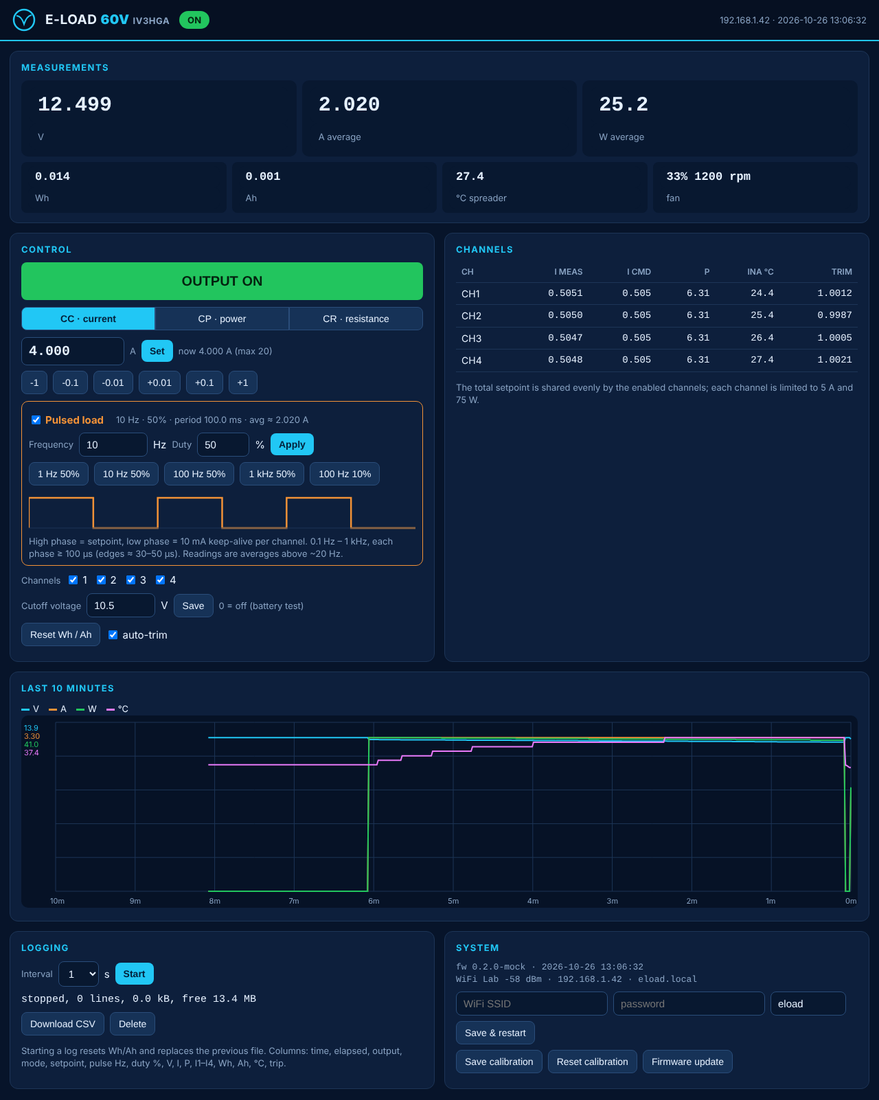
firmware 0.2.0 — pulsed load (frequency 0.1 Hz – 1 kHz, duty 1 – 99 %, phases ≥ 100 µs) in the panel menu, the web page, the API and the CSV.
firmware 0.1.0 — first firmware: control, protections, OLED + encoder panel, CSV logging, web interface, OTA.
rev 0.3 — front panel: PCF8574 expander, 10-pin IDC connector, debounce, I²C pull-ups 2.2 kΩ. Schematic and PCB translated to English (sheets: input, channels, control, power). Silkscreen cleaned up: no overlaps, references next to their parts; interactive BOM and assembly drawings.
rev 0.2 — loop compensation C6 = 1 nF, setpoint filter C5 = 10 nF (10× bandwidth, PM ≈ 80°); WiFi control with D1 mini Pro replaces STM32 + isolated USB.
Inspired by shufps/eload2. Designed by IV3HGA.
hardware/ and docs/): CERN-OHL-S-2.0 — see LICENSE.firmware/, analysis/, tools/): MIT — see LICENSE-MIT.| Qty | Value | Footprint | References |
|---|---|---|---|
| 15 | 100n | Capacitor_SMD:C_1206_3216Metric | C3, C4, C7, C10, C13, C16, C20, C22, C28, C29, C30, C32, C33, C34, C36 |
| 15 | 10k | Resistor_SMD:R_1206_3216Metric | R2, R5, R8, R16, R22, R28, R34, R39, R40, R41, R42, R44, R46, R48, R51 |
| 7 | 1k | Resistor_SMD:R_1206_3216Metric | R4, R14, R20, R26, R32, R36, R45 |
| 6 | 100R | Resistor_SMD:R_1206_3216Metric | R1, R15, R21, R27, R33, R49 |
| 6 | 10u 25V | Capacitor_SMD:C_1206_3216Metric | C19, C21, C27, C35, C38, C39 |
| 4 | 100k | Resistor_SMD:R_1206_3216Metric | R10, R47, R50, R55 |
| 4 | 100n 50V | Capacitor_SMD:C_1206_3216Metric | C17, C18, C40, C41 |
| 4 | 10n | Capacitor_SMD:C_1206_3216Metric | C23, C24, C25, C26 |
| 4 | 10n C0G | Capacitor_SMD:C_1206_3216Metric | C5, C8, C11, C14 |
| 4 | 1k 0.1% | Resistor_SMD:R_1206_3216Metric | R13, R19, R25, R31 |
| 4 | 1n C0G | Capacitor_SMD:C_1206_3216Metric | C6, C9, C12, C15 |
| 4 | 20m 1% | Resistor_SMD:R_Shunt_Vishay_WSK2512_6332Metric_T1.19mm | R17, R23, R29, R35 |
| 4 | 24k 0.1% | Resistor_SMD:R_1206_3216Metric | R12, R18, R24, R30 |
| 4 | INA228 | Package_SO:MSOP-10_3x3mm_P0.5mm | U4, U5, U7, U8 |
| 4 | IXTH75N10L2 | Package_TO_SOT_THT:TO-247-3_Horizontal_TabUp | Q1, Q2, Q3, Q4 |
| 4 | M3 | MountingHole_3.2mm_M3 | H1, H2, H3, H4 |
| 4 | M3 nylon (spreader) | MountingHole_3.2mm_M3 | H5, H6, H7, H8 |
| 3 | FDS9926A | Package_SO:SOIC-8_3.9x4.9mm_P1.27mm | Q5, Q6, Q7 |
| 2 | 10k 0.1% | Resistor_SMD:R_1206_3216Metric | R52, R53 |
| 2 | 1M | Resistor_SMD:R_1206_3216Metric | R6, R9 |
| 2 | 1u | Capacitor_SMD:C_1206_3216Metric | C31, C37 |
| 2 | 22u 10V | Capacitor_SMD:C_1206_3216Metric | C42, C43 |
| 2 | 2k2 | Resistor_SMD:R_1206_3216Metric | R37, R38 |
| 2 | OPA2196 | Package_SO:SOIC-8_3.9x4.9mm_P1.27mm | U3, U6 |
| 1 | 1.5A | Fuse:Fuse_1206_3216Metric | F2 |
| 1 | 100n 100V | Capacitor_SMD:C_1206_3216Metric | C1 |
| 1 | 10R | Resistor_SMD:R_1206_3216Metric | R3 |
| 1 | 10n 100V | Capacitor_SMD:C_1206_3216Metric | C2 |
| 1 | 12V DC | Connector_BarrelJack:BarrelJack_Horizontal | J9 |
| 1 | 1k5 | Resistor_SMD:R_1206_3216Metric | R54 |
| 1 | 249k | Resistor_SMD:R_1206_3216Metric | R7 |
| 1 | 25A ATO | Fuse:Fuseholder_Blade_ATO_Littelfuse_Pudenz_2_Pin | F1 |
| 1 | 470R | Resistor_SMD:R_1206_3216Metric | R43 |
| 1 | 6u8 | Inductor_SMD:L_Bourns-SRN4018 | L1 |
| 1 | 9k31 | Resistor_SMD:R_1206_3216Metric | R11 |
| 1 | AP63205WU | Package_TO_SOT_SMD:TSOT-23-6 | U12 |
| 1 | D1mini L | Connector_PinSocket_2.54mm:PinSocket_1x08_P2.54mm_Vertical | J4 |
| 1 | D1mini R | Connector_PinSocket_2.54mm:PinSocket_1x08_P2.54mm_Vertical | J5 |
| 1 | DAC8565 | Package_SO:TSSOP-16_4.4x5mm_P0.65mm | U10 |
| 1 | DUT+ | MountingHole:MountingHole_5.3mm_M5_Pad_Via | J1 |
| 1 | DUT- | MountingHole:MountingHole_5.3mm_M5_Pad_Via | J2 |
| 1 | FAN | Connector_Molex:Molex_KK-254_AE-6410-04A_1x04_P2.54mm_Vertical | J7 |
| 1 | FRONT PANEL | Connector_IDC:IDC-Header_2x05_P2.54mm_Vertical | J6 |
| 1 | L78L05 | Package_SO:SOIC-8_3.9x4.9mm_P1.27mm | U11 |
| 1 | LM393 | Package_SO:SOIC-8_3.9x4.9mm_P1.27mm | U2 |
| 1 | Logo_IV3HGA | eload:Logo_IV3HGA_25mm | LOGO1 |
| 1 | NTC | Connector_Molex:Molex_KK-254_AE-6410-04A_1x04_P2.54mm_Vertical | J8 |
| 1 | PCF8574T | Package_SO:SOIC-16W_7.5x10.3mm_P1.27mm | U9 |
| 1 | SENSE | TerminalBlock_Phoenix:TerminalBlock_Phoenix_MKDS-1,5-2_1x02_P5.00mm_Horizontal | J3 |
| 1 | SMAJ64CA | Diode_SMD:D_SMA | D3 |
| 1 | SMCJ64CA | Diode_SMD:D_SMC | D2 |
| 1 | SS34 | Diode_SMD:D_SMA | D4 |
| 1 | TL431ID | Package_SO:SOIC-8_3.9x4.9mm_P1.27mm | U1 |
| 1 | VS-30CTQ100S | Package_TO_SOT_SMD:TO-263-2 | D1 |
| 1 | green | LED_SMD:LED_1206_3216Metric | D5 |
dganin-hw/bldc-foc
Контроллер бесколлекторного мотора с FOC на STM32G431: своя силовая плата, плата энкодера AS5047P, печатный стенд и прошивка на C

vehiclewaxberry/Space-Embodied-Robot-Complete
航天服务星具身智能机械臂机器人 | Space Service Robot with Embodied Intelligence — mechanical, electrical & harness, power & thermal, and propulsion hardware design.


ericyuanyong/asset-tracker
a asset tracker demo project based on msom


Lafayette-FSAE/Carman-2021
CarMan kiCad schematics and libraries. Boards include GLV, Logic, Pi Shield, TSI. Also includes drawings for EPAL, and SLOOP.

It measures 170 × 125 mm and has 2 copper layers, 1.6 mm thick.
143 parts, built around the OPA2196ID, AP63205WU, DAC8565IAPW and L78L05ACD13TR-MS. The full list of its parts is on this page, with links to each part's symbol and footprint where PCBKit's library has them.
From the metallarox/eload-60v repository on GitHub, at the commit this page was made from: the board is hardware/kicad/eload_4ch.kicad_pcb and its schematic hardware/kicad/channels.kicad_sch. PCBKit opens the board in the browser, with nothing to install.
Its repository publishes it under the CERN-OHL-S-2.0 licence: you may reuse it on that licence's terms (keep the author's notice, and for a copyleft licence share your changes alike).