2 layers191.5 × 116 mm
PiDaughterBoard
mekatrol/electronics
This repository contains the electronics, embedded firmware, support software, and reference material for a collection of home-automation and workshop projects.
175 parts

 mekatrol/electronics
This repository contains the electronics, embedded firmware, support software, and reference material for a collection of home-automation and workshop projects.
Iw-8-controller is an open-source printed circuit board by mekatrol, from the mekatrol/electronics repository on GitHub. It is a 2-layer board of 167.3 × 103 mm with 212 parts on 147 nets, routed with 991 tracks and 381 vias.
It is built around the BT136S, LM2576S-12 and LM324, with the W25Q128JVSIQ, 74HCT595D and AMS1117-3.3 among its other parts. Its parts include 54 resistors, 43 diodes, 22 connectors, 21 capacitors and 11 ICs. It belongs with the RP2040 boards of this library.


This repository contains the electronics, embedded firmware, support software, and reference material for a collection of home-automation and workshop projects. Hardware designs are primarily created with KiCad, firmware targets Raspberry Pi Pico/Pico W and MicroPython-compatible boards, and the host-side controller tools are written in .NET, C++, and Python.
.
├── firmware/              Embedded C/C++, Arduino, and MicroPython projects
├── hardware/              KiCad projects, libraries, footprints, and 3D models
├── software/              Desktop, command-line, monitoring, and test tools
├── irrigation_wiring.txt  Irrigation wiring notes
└── README.md              Repository overview
Generated build output, IDE state, KiCad backup/session files, and caches are excluded by .gitignore.
Each board directory contains its KiCad project (.kicad_pro), schematic (.kicad_sch), and PCB layout (.kicad_pcb) where applicable. Some projects also include manufacturing Gerber archives or exported 3D models.
| Project | Location | Description |
|---|---|---|
| Basic controller | hardware/basic_controller/ | General-purpose controller board with a hierarchical CPU schematic. |
| IW-8 expansion | hardware/iw-8-expansion/ | Expansion board with separate power and output schematic sheets. |
| LED controller | hardware/led_controller/ | Controller board for LED loads. |
| Output board | hardware/output_board/ | Standalone output-control board. |
| Pico controller | hardware/pico/controller/ | Raspberry Pi Pico-based controller with CPU, input, output, power, and control-panel designs. |
| Pico IW-8 controller | hardware/pico/iw-8-controller/ | Pico-based IW-8 controller with input, output, power, and CPU sheets. |
| Pico output controller | hardware/pico/output_controller/ | Pico output controller with two output banks and supporting input and power circuitry. |
| RS-485 board | hardware/rs485_board/ | RS-485 interface board. |
| Temperature controller | hardware/temperature_controller/ | Temperature-control PCB and exported 3D model. |
| Triac/FET module | hardware/triac_fet_module/ | Mains-load switching module using an optically isolated zero-cross triac, with KiCad design rules and Gerber/CNC manufacturing files. |
| WS2812 segment | hardware/ws2812_segment/ | PCB segment for WS2812 addressable LEDs. |
Shared hardware resources include:
hardware/kicad/ — the canonical KiCad resource tree, containing symbols, footprints, Python modules, and action plugins.hardware/fusion360_modules/ — Fusion 360 helper scripts.hardware/pcb-checklist.xlsx — PCB design/review checklist.Open a hardware project by loading its .kicad_pro file in KiCad. Keep the repository layout intact so that relative library and 3D-model references continue to resolve.
Use hardware/kicad/modules/generate_jlcpcb.py to generate the fabrication and
assembly files for a board. Run it from the repository root and pass the name of
the project under hardware/. For example, to generate the LED controller:
python3 hardware/kicad/modules/generate_jlcpcb.py led_controllerThe project argument selects which board is generated; it is not hard-coded in
the script. A full project directory, .kicad_pro file, or .kicad_pcb file
can also be supplied, for example
hardware/led_controller/led_controller.kicad_pro.
The script requires KiCad 7 or newer. It automatically finds a native
kicad-cli executable or the org.kicad.KiCad Flatpak. For another
installation, provide the executable explicitly:
python3 hardware/kicad/modules/generate_jlcpcb.py \
  --kicad-cli /path/to/kicad-cli led_controller
Files are written to a gerber/ directory beside the board. For a project
named led_controller, the upload files are:
| File | JLCPCB upload field | Contents |
|---|---|---|
gerber/led_controller-gerbers.zip | PCB Gerber file | Copper, solder-mask, silkscreen, board-outline, paste, and drill files. |
gerber/led_controller-bom.csv | BOM file | Parts having a non-empty LCSC Part # schematic field. |
gerber/led_controller-positions.csv | CPL file | Component centroid/pick-and-place data. |
The Gerber ZIP is generated automatically. Do not add the BOM and CPL to that ZIP: JLCPCB expects the fabrication ZIP, BOM, and CPL as three separate uploads when ordering assembled boards. For a bare PCB order, only the Gerber ZIP is required.
The generator uses these JLCPCB-compatible export settings:
Edge.Cuts.Designator, Mid X, Mid Y,
Rotation, and Layer, with the sides written as Top and Bottom.Comment, Designator, Footprint, and LCSC Part #.
Identical parts are grouped, and symbols without an LCSC Part # are omitted.Always inspect the uploaded board preview, part matches, placement rotations, and board side in JLCPCB before submitting an order. Component-specific rotation corrections are not applied automatically by this script.
The root firmware/CMakeLists.txt configures a Pico W build using CMake and the Raspberry Pi Pico SDK. It currently includes these targets:
| Target | Location | Purpose |
|---|---|---|
iw_8_controller | firmware/iw_8_controller/ | Main C++ IW-8 controller firmware, including messaging, flows, storage, RTC, and PIO-driven outputs. |
memory_management_testing | firmware/memory_management_testing/ | Test target for the custom memory-management implementation. |
uart_testing | firmware/uart_testing/ | Test target for serial/UART communication. |
Reusable Pico code lives in firmware/common/ and covers communication, memory management, PIO, RTC, flash storage, CRC, I2C, inter-core synchronization, and general utilities.
To configure and build the Pico SDK targets:
export PICO_SDK_PATH=/path/to/pico-sdk
cmake -S firmware -B firmware/build
cmake --build firmware/build
The project requires Pico SDK 1.3.0 or later and uses C11 and C++17.
| Project | Location | Description |
|---|---|---|
| Garage monitor | firmware/garage_monitor/ | Networked garage monitor with mmWave sensing and NeoPixel support. |
| IW-8 controller prototype | firmware/iw_8_controller_python/ | Python implementation/prototype of the IW-8 controller. |
| mmWave sensor | firmware/mmwave_sensor/ | Networked mmWave sensor firmware with MQTT and NeoPixel support. |
| Simple controller | firmware/simple_controller/ | Small networked controller with sensor and NeoPixel helpers. |
| Wall sensor | firmware/wall_sensor/ | Wall-sensor firmware with WLAN, I2C, and NeoPixel helpers. |
Device-specific config.py files hold each firmware project's configuration. Review these before deploying to a board and avoid committing private credentials.
| Project | Location | Description |
|---|---|---|
| Fish feeder | firmware/fish_feeder/ | Fish-feeder control using a stepper motor; Arduino and Python implementations are present. |
| Reflow controller | firmware/reflow_controller/ | Reflow-oven controller with temperature sensing, PID control, stages, plotting, learning, and LCD/UI code. |
firmware/bluetooth_test/ contains Python Bluetooth client and server test programs.firmware/rp2040_registers.docx is an RP2040 register reference.firmware/common/communication/ defines the device communication and message protocol shared by firmware components.software/Controller/Controller.sln is a Visual Studio/.NET 6 solution containing:
| Project | Description |
|---|---|
HomeAutomation.Common | Shared configuration, dependency-injection, logging, serial communication, protocol, and message implementations. |
HomeAutomation.ControllerCLI | Command-line controller application built on the common library. |
HomeAutomation.Monitor | Configurable monitoring process; includes application settings and a service definition. |
HomeAutomation.Terminal | Serial terminal utility. |
Build the solution with:
dotnet build software/Controller/Controller.slnsoftware/CodeTestHarness/ is a Visual C++ test harness for native code experiments.software/mmwave_sensor/ is a Python serial/data-analysis utility using pyserial and numpy.Install the Python utility dependencies with:
python -m pip install -r software/mmwave_sensor/requirements.txtirrigation_wiring.txt documents irrigation-system wiring.build, bin, obj, cache, or automatic backup directories.hardware/pcb-checklist.xlsx before ordering boards.| Qty | Value | Footprint | References |
|---|---|---|---|
| 18 | 1K | Resistor_SMD:R_1206_3216Metric | R1, R2, R29, R30, R31, R32, R33, R34, R35, R36, R37, R38, R39, R40, R41, R42 +2 |
| 16 | 100R | Resistor_SMD:R_1206_3216Metric | R4, R7, R8, R11, R12, R13, R14, R17, R18, R21, R22, R24, R25, R26, R27, R28 |
| 13 | 100n | Capacitor_SMD:C_1206_3216Metric | C1, C2, C4, C5, C13, C14, C15, C16, C17, C18, C19, C20, C21 |
| 12 | SparkGap | FootprintLibrary:Arc Spark Gap | E1, E2, E3, E4, E5, E6, E7, E8, E9, E10, E11, E12 |
| 11 | 10K | Resistor_SMD:R_1206_3216Metric | R3, R5, R9, R19, R20, R23, R47, R48, R51, R52, R53 |
| 10 | CON2 | TerminalBlock_Phoenix:TerminalBlock_Phoenix_MKDS-1,5-2-5.08_1x02_P5.08mm_Horizontal | J3, J4, J15, J16, J17, J18, J19, J20, J21, J22 |
| 10 | MountingHole_Pad | MountingHole:MountingHole_3.2mm_M3_Pad_Via | H1, H2, H3, H4, H5, H6, H7, H8, H9, H10 |
| 9 | 4.7K | Resistor_SMD:R_1206_3216Metric | R6, R10, R15, R16, R45, R46, R49, R50, R54 |
| 9 | LED | LED_SMD:LED_0805_2012Metric_Pad1.15x1.40mm_HandSolder | D3, D21, D22, D23, D30, D31, D32, D37, D38 |
| 9 | SMAJ48CA | Diode_SMD:D_SMA | D11, D15, D16, D17, D24, D25, D26, D33, D34 |
| 9 | SolderJumper_2_Bridged | Jumper:SolderJumper-2_P1.3mm_Bridged2Bar_RoundedPad1.0x1.5mm | JP1, JP7, JP8, JP9, JP13, JP14, JP15, JP18, JP19 |
| 8 | BT136S | Package_TO_SOT_SMD:TO-252-3_TabPin2 | D18, D19, D20, D27, D28, D29, D35, D36 |
| 8 | HXY2102EI | FootprintLibrary:SOT-323_ALTERNATE_PIN_NUMBER | Q2, Q3, Q4, Q5, Q6, Q7, Q8, Q9 |
| 8 | Jumper_3_Open | Connector_PinHeader_2.54mm:PinHeader_1x03_P2.54mm_Vertical | JP4, JP5, JP6, JP10, JP11, JP12, JP16, JP17 |
| 6 | MBR120 | Diode_SMD:D_SOD-123 | D1, D2, D6, D7, D39, D40 |
| 6 | US1M 1A | Diode_SMD:D_SMA | D4, D5, D8, D9, D10, D14 |
| 5 | 3V3 | Package_TO_SOT_SMD:SOT-23 | D12, D13, D41, D42, D43 |
| 5 | Conn_01x04_Male | Connector_JST:JST_PH_B4B-PH-K_1x04_P2.00mm_Vertical | J1, J7, J8, J9, J11 |
| 4 | 4.7u | Capacitor_SMD:CP_Elec_6.3x5.4 | C7, C8, C9, C12 |
| 4 | Fiducial | Fiducial:Fiducial_1mm_Mask2mm | FID1, FID2, FID3, FID4 |
| 3 | 220u | Capacitor_SMD:CP_Elec_6.3x7.7 | C3, C6, C10 |
| 2 | Conn_01x04_Female | Connector_PinSocket_2.54mm:PinSocket_1x04_P2.54mm_Vertical | J12, J13 |
| 2 | EL3H7 | Package_SO:SOP-4_4.4x2.6mm_P1.27mm | U9, U10 |
| 2 | Fuse_Small | Fuse:Fuse_Blade_ATO_directSolder | F1, F2 |
| 2 | Jumper_2_Open | Connector_PinHeader_2.54mm:PinHeader_1x02_P2.54mm_Vertical | JP2, JP3 |
| 1 | +12V | TerminalBlock_Phoenix:TerminalBlock_Phoenix_MKDS-1,5-2-5.08_1x02_P5.08mm_Horizontal | J2 |
| 1 | 1000u | Capacitor_SMD:CP_Elec_16x17.5 | C11 |
| 1 | 100u | Inductor_SMD:L_1206_3216Metric | L1 |
| 1 | 24-26VAC | TerminalBlock_Phoenix:TerminalBlock_Phoenix_MKDS-1,5-2-5.08_1x02_P5.08mm_Horizontal | J5 |
| 1 | 32.768kHz SMD Crystal Resonator | Crystal:Crystal_SMD_3215-2Pin_3.2x1.5mm | Y1 |
| 1 | 74HCT595 | Package_SO:SOIC-16_3.9x9.9mm_P1.27mm | U8 |
| 1 | AMS1117-3.3 | Package_TO_SOT_SMD:SOT-223-3_TabPin2 | U2 |
| 1 | AMS1117-5.0 | Package_TO_SOT_SMD:SOT-223-3_TabPin2 | U1 |
| 1 | AO3401A | Package_TO_SOT_SMD:SOT-23 | Q1 |
| 1 | CR2032 | Battery:BatteryHolder_Keystone_1058_1x2032 | BT1 |
| 1 | Conn_01x03_Male | Connector_PinHeader_2.54mm:PinHeader_1x03_P2.54mm_Vertical | J10 |
| 1 | Conn_02x10_Odd_Even | Connector_IDC:IDC-Header_2x10_P2.54mm_Vertical | J14 |
| 1 | DS1307ZN+ | Package_SO:SOIC-8_3.9x4.9mm_P1.27mm | U5 |
| 1 | GND | TerminalBlock_Phoenix:TerminalBlock_Phoenix_MKDS-1,5-2-5.08_1x02_P5.08mm_Horizontal | J6 |
| 1 | LM2576S-12 | Package_TO_SOT_SMD:TO-263-5_TabPin3 | U3 |
| 1 | LM324 | Package_SO:SOIC-14_3.9x8.7mm_P1.27mm | U11 |
| 1 | Pico | RPi_Pico:RPi_Pico_SMD_TH_No_SWD | U7 |
| 1 | STWD100 | Package_TO_SOT_SMD:SOT-23-5 | U4 |
| 1 | TS-1187A-B-A-B Push Button | Button_Switch_SMD:SW_SPST_TL3342 | SW1 |
| 1 | TestPoint_2Pole | TestPoint:TestPoint_2Pads_Pitch5.08mm_Drill1.3mm | TP1 |
| 1 | W25Q128JVS | Package_SO:SOIC-8_5.23x5.23mm_P1.27mm | U6 |
It measures 167.3 × 103 mm and has 2 copper layers, 1.6 mm thick.
212 parts, built around the BT136S, LM2576S-12, LM324 and W25Q128JVSIQ. The full list of its parts is on this page, with links to each part's symbol and footprint where PCBKit's library has them.
From the mekatrol/electronics repository on GitHub, at the commit this page was made from: the board is hardware/iw-8-controller/iw-8-controller.kicad_pcb. PCBKit opens the board in the browser, with nothing to install.
Its repository states no licence, so its author keeps all rights: ask mekatrol before reusing the design.
mekatrol/electronics
This repository contains the electronics, embedded firmware, support software, and reference material for a collection of home-automation and workshop projects.

mekatrol/electronics
This repository contains the electronics, embedded firmware, support software, and reference material for a collection of home-automation and workshop projects.

mekatrol/electronics
This repository contains the electronics, embedded firmware, support software, and reference material for a collection of home-automation and workshop projects.

mekatrol/electronics
This repository contains the electronics, embedded firmware, support software, and reference material for a collection of home-automation and workshop projects.

mekatrol/electronics
This repository contains the electronics, embedded firmware, support software, and reference material for a collection of home-automation and workshop projects.

mekatrol/electronics
This repository contains the electronics, embedded firmware, support software, and reference material for a collection of home-automation and workshop projects.
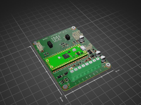
mekatrol/electronics
This repository contains the electronics, embedded firmware, support software, and reference material for a collection of home-automation and workshop projects.

mekatrol/electronics
This repository contains the electronics, embedded firmware, support software, and reference material for a collection of home-automation and workshop projects.

mekatrol/electronics
This repository contains the electronics, embedded firmware, support software, and reference material for a collection of home-automation and workshop projects.

mekatrol/electronics
This repository contains the electronics, embedded firmware, support software, and reference material for a collection of home-automation and workshop projects.

mekatrol/electronics
This repository contains the electronics, embedded firmware, support software, and reference material for a collection of home-automation and workshop projects.

mekatrol/electronics
This repository contains the electronics, embedded firmware, support software, and reference material for a collection of home-automation and workshop projects.

MR-DOS/MWGEN-G1
12.5 MHz - 6400 MHz (LMX2572) or even up to 20 GHz (LMX2595) generator board with int./ext. reference.


dangrie158/AmpStation
A Class D audio amplifier in a n old Teufel Decoder Station 5 case


mekanii/ESU
Below is the output scope from the sense circuit, where the pad resistance values are 5Ω, 200Ω, 1kΩ, and High Impedance.

