2 layers167.3 × 103 mm
Iw-8-controller
mekatrol/electronics
This repository contains the electronics, embedded firmware, support software, and reference material for a collection of home-automation and workshop projects.
212 parts

 mekatrol/electronics
This repository contains the electronics, embedded firmware, support software, and reference material for a collection of home-automation and workshop projects.
Mek core ctrl is an open-source printed circuit board by mekatrol, from the mekatrol/electronics repository on GitHub. It is a 2-layer board of 150 × 100 mm with 17 parts on 11 nets.
It is built around the AMS1117-3.3, MBR120 and SMAJ48CA. Its parts include 8 capacitors, 3 diodes, 2 ICs, 1 resistor and 1 connector.


This repository contains the electronics, embedded firmware, support software, and reference material for a collection of home-automation and workshop projects. Hardware designs are primarily created with KiCad, firmware targets Raspberry Pi Pico/Pico W and MicroPython-compatible boards, and the host-side controller tools are written in .NET, C++, and Python.
.
├── firmware/              Embedded C/C++, Arduino, and MicroPython projects
├── hardware/              KiCad projects, libraries, footprints, and 3D models
├── software/              Desktop, command-line, monitoring, and test tools
├── irrigation_wiring.txt  Irrigation wiring notes
└── README.md              Repository overview
Generated build output, IDE state, KiCad backup/session files, and caches are excluded by .gitignore.
Each board directory contains its KiCad project (.kicad_pro), schematic (.kicad_sch), and PCB layout (.kicad_pcb) where applicable. Some projects also include manufacturing Gerber archives or exported 3D models.
| Project | Location | Description |
|---|---|---|
| Basic controller | hardware/basic_controller/ | General-purpose controller board with a hierarchical CPU schematic. |
| IW-8 expansion | hardware/iw-8-expansion/ | Expansion board with separate power and output schematic sheets. |
| LED controller | hardware/led_controller/ | Controller board for LED loads. |
| Output board | hardware/output_board/ | Standalone output-control board. |
| Pico controller | hardware/pico/controller/ | Raspberry Pi Pico-based controller with CPU, input, output, power, and control-panel designs. |
| Pico IW-8 controller | hardware/pico/iw-8-controller/ | Pico-based IW-8 controller with input, output, power, and CPU sheets. |
| Pico output controller | hardware/pico/output_controller/ | Pico output controller with two output banks and supporting input and power circuitry. |
| RS-485 board | hardware/rs485_board/ | RS-485 interface board. |
| Temperature controller | hardware/temperature_controller/ | Temperature-control PCB and exported 3D model. |
| Triac/FET module | hardware/triac_fet_module/ | Mains-load switching module using an optically isolated zero-cross triac, with KiCad design rules and Gerber/CNC manufacturing files. |
| WS2812 segment | hardware/ws2812_segment/ | PCB segment for WS2812 addressable LEDs. |
Shared hardware resources include:
hardware/kicad/ — the canonical KiCad resource tree, containing symbols, footprints, Python modules, and action plugins.hardware/fusion360_modules/ — Fusion 360 helper scripts.hardware/pcb-checklist.xlsx — PCB design/review checklist.Open a hardware project by loading its .kicad_pro file in KiCad. Keep the repository layout intact so that relative library and 3D-model references continue to resolve.
Use hardware/kicad/modules/generate_jlcpcb.py to generate the fabrication and
assembly files for a board. Run it from the repository root and pass the name of
the project under hardware/. For example, to generate the LED controller:
python3 hardware/kicad/modules/generate_jlcpcb.py led_controllerThe project argument selects which board is generated; it is not hard-coded in
the script. A full project directory, .kicad_pro file, or .kicad_pcb file
can also be supplied, for example
hardware/led_controller/led_controller.kicad_pro.
The script requires KiCad 7 or newer. It automatically finds a native
kicad-cli executable or the org.kicad.KiCad Flatpak. For another
installation, provide the executable explicitly:
python3 hardware/kicad/modules/generate_jlcpcb.py \
  --kicad-cli /path/to/kicad-cli led_controller
Files are written to a gerber/ directory beside the board. For a project
named led_controller, the upload files are:
| File | JLCPCB upload field | Contents |
|---|---|---|
gerber/led_controller-gerbers.zip | PCB Gerber file | Copper, solder-mask, silkscreen, board-outline, paste, and drill files. |
gerber/led_controller-bom.csv | BOM file | Parts having a non-empty LCSC Part # schematic field. |
gerber/led_controller-positions.csv | CPL file | Component centroid/pick-and-place data. |
The Gerber ZIP is generated automatically. Do not add the BOM and CPL to that ZIP: JLCPCB expects the fabrication ZIP, BOM, and CPL as three separate uploads when ordering assembled boards. For a bare PCB order, only the Gerber ZIP is required.
The generator uses these JLCPCB-compatible export settings:
Edge.Cuts.Designator, Mid X, Mid Y,
Rotation, and Layer, with the sides written as Top and Bottom.Comment, Designator, Footprint, and LCSC Part #.
Identical parts are grouped, and symbols without an LCSC Part # are omitted.Always inspect the uploaded board preview, part matches, placement rotations, and board side in JLCPCB before submitting an order. Component-specific rotation corrections are not applied automatically by this script.
The root firmware/CMakeLists.txt configures a Pico W build using CMake and the Raspberry Pi Pico SDK. It currently includes these targets:
| Target | Location | Purpose |
|---|---|---|
iw_8_controller | firmware/iw_8_controller/ | Main C++ IW-8 controller firmware, including messaging, flows, storage, RTC, and PIO-driven outputs. |
memory_management_testing | firmware/memory_management_testing/ | Test target for the custom memory-management implementation. |
uart_testing | firmware/uart_testing/ | Test target for serial/UART communication. |
Reusable Pico code lives in firmware/common/ and covers communication, memory management, PIO, RTC, flash storage, CRC, I2C, inter-core synchronization, and general utilities.
To configure and build the Pico SDK targets:
export PICO_SDK_PATH=/path/to/pico-sdk
cmake -S firmware -B firmware/build
cmake --build firmware/build
The project requires Pico SDK 1.3.0 or later and uses C11 and C++17.
| Project | Location | Description |
|---|---|---|
| Garage monitor | firmware/garage_monitor/ | Networked garage monitor with mmWave sensing and NeoPixel support. |
| IW-8 controller prototype | firmware/iw_8_controller_python/ | Python implementation/prototype of the IW-8 controller. |
| mmWave sensor | firmware/mmwave_sensor/ | Networked mmWave sensor firmware with MQTT and NeoPixel support. |
| Simple controller | firmware/simple_controller/ | Small networked controller with sensor and NeoPixel helpers. |
| Wall sensor | firmware/wall_sensor/ | Wall-sensor firmware with WLAN, I2C, and NeoPixel helpers. |
Device-specific config.py files hold each firmware project's configuration. Review these before deploying to a board and avoid committing private credentials.
| Project | Location | Description |
|---|---|---|
| Fish feeder | firmware/fish_feeder/ | Fish-feeder control using a stepper motor; Arduino and Python implementations are present. |
| Reflow controller | firmware/reflow_controller/ | Reflow-oven controller with temperature sensing, PID control, stages, plotting, learning, and LCD/UI code. |
firmware/bluetooth_test/ contains Python Bluetooth client and server test programs.firmware/rp2040_registers.docx is an RP2040 register reference.firmware/common/communication/ defines the device communication and message protocol shared by firmware components.software/Controller/Controller.sln is a Visual Studio/.NET 6 solution containing:
| Project | Description |
|---|---|
HomeAutomation.Common | Shared configuration, dependency-injection, logging, serial communication, protocol, and message implementations. |
HomeAutomation.ControllerCLI | Command-line controller application built on the common library. |
HomeAutomation.Monitor | Configurable monitoring process; includes application settings and a service definition. |
HomeAutomation.Terminal | Serial terminal utility. |
Build the solution with:
dotnet build software/Controller/Controller.slnsoftware/CodeTestHarness/ is a Visual C++ test harness for native code experiments.software/mmwave_sensor/ is a Python serial/data-analysis utility using pyserial and numpy.Install the Python utility dependencies with:
python -m pip install -r software/mmwave_sensor/requirements.txtirrigation_wiring.txt documents irrigation-system wiring.build, bin, obj, cache, or automatic backup directories.hardware/pcb-checklist.xlsx before ordering boards.| Qty | Value | Footprint | References |
|---|---|---|---|
| 4 | 100n | Capacitor_SMD:C_1206_3216Metric | C1, C2, C3, C8 |
| 2 | 220u | Capacitor_SMD:CP_Elec_6.3x7.7 | C6, C9 |
| 1 | 1000u | Capacitor_THT:CP_Radial_D16.0mm_P7.50mm | C4 |
| 1 | 100k | Resistor_SMD:R_1206_3216Metric | R1 |
| 1 | 24-26VAC | TerminalBlock_Phoenix:TerminalBlock_Phoenix_MKDS-1,5-2-5.08_1x02_P5.08mm_Horizontal | J1 |
| 1 | 4.7u | Capacitor_SMD:CP_Elec_6.3x5.4 | C7 |
| 1 | AMS1117-3.3 | Package_TO_SOT_SMD:SOT-223-3_TabPin2 | U2 |
| 1 | Fuse_Small | Fuse:Fuse_Blade_ATO_directSolder | F1 |
| 1 | LMR38020FDDAR | TI LMR38020FDDAR:DDA0008E-IPC_A | U1 |
| 1 | MBR120 | Diode_SMD:D_SOD-123 | D2 |
| 1 | SMAJ48CA | Diode_SMD:D_SMA | D1 |
| 1 | TestPoint_2Pole | TestPoint:TestPoint_2Pads_Pitch5.08mm_Drill1.3mm | TP1 |
| 1 | US1M 1A | Diode_SMD:D_SMA | D3 |
It measures 150 × 100 mm and has 2 copper layers, 1.6 mm thick.
17 parts, built around the AMS1117-3.3, MBR120 and SMAJ48CA. The full list of its parts is on this page, with links to each part's symbol and footprint where PCBKit's library has them.
From the mekatrol/electronics repository on GitHub, at the commit this page was made from: the board is hardware/mek-core-ctrl/mek-core-ctrl.kicad_pcb. PCBKit opens the board in the browser, with nothing to install.
Its repository states no licence, so its author keeps all rights: ask mekatrol before reusing the design.
mekatrol/electronics
This repository contains the electronics, embedded firmware, support software, and reference material for a collection of home-automation and workshop projects.

mekatrol/electronics
This repository contains the electronics, embedded firmware, support software, and reference material for a collection of home-automation and workshop projects.

mekatrol/electronics
This repository contains the electronics, embedded firmware, support software, and reference material for a collection of home-automation and workshop projects.

mekatrol/electronics
This repository contains the electronics, embedded firmware, support software, and reference material for a collection of home-automation and workshop projects.

mekatrol/electronics
This repository contains the electronics, embedded firmware, support software, and reference material for a collection of home-automation and workshop projects.

mekatrol/electronics
This repository contains the electronics, embedded firmware, support software, and reference material for a collection of home-automation and workshop projects.

mekatrol/electronics
This repository contains the electronics, embedded firmware, support software, and reference material for a collection of home-automation and workshop projects.
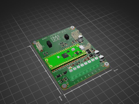
mekatrol/electronics
This repository contains the electronics, embedded firmware, support software, and reference material for a collection of home-automation and workshop projects.

mekatrol/electronics
This repository contains the electronics, embedded firmware, support software, and reference material for a collection of home-automation and workshop projects.

mekatrol/electronics
This repository contains the electronics, embedded firmware, support software, and reference material for a collection of home-automation and workshop projects.

mekatrol/electronics
This repository contains the electronics, embedded firmware, support software, and reference material for a collection of home-automation and workshop projects.

mekatrol/electronics
This repository contains the electronics, embedded firmware, support software, and reference material for a collection of home-automation and workshop projects.

MR-DOS/MWGEN-G1
12.5 MHz - 6400 MHz (LMX2572) or even up to 20 GHz (LMX2595) generator board with int./ext. reference.


joeycastillo/The-Open-Book
For details on how to build, test and use Open Book, I've made documentation available here.

ElectronicCats/Minino
Minino is an original multiprotocol and multiband board made for sniffing, communicating, and attacking IoT devices. It was designed as a mini Cat that integrates the powerful ESP32C6, GPS, microSD and OLED.

LouDnl/USBSID-Pico
USBSID-Pico is a RPi Pico (RP2040/W RP2350/W) based board for interfacing one or two MOS SID chips and/or hardware SID emulators over (WEB)USB with your computer, phone, ASID supporting player or USB midi controller

jpconstantineau/NRF52-Board
This Repository is a collection of NRF5x boards.

