2 layers60 × 30 mm
Controller
google/mozc-devices
Circuit diagrams and firmware source code for Gboard DIY keyboards
11 parts3kApache-2.0

 Md-shiraz/555Timer-PCB-Design
A KiCad hardware project for an adjustable 555-timer-driven DC motor switch. An LM555 generates a control signal, and an N-channel MOSFET switches the motor on the low side.
555Timer is an open-source printed circuit board by Md-shiraz, from the Md-shiraz/555Timer-PCB-Design repository on GitHub. It is a 2-layer board with 11 parts on 10 nets, routed with 20 tracks and 0 vias.
Its parts include 3 resistors, 2 capacitors, 2 diodes, 1 IC and 1 transistor.
A KiCad hardware project for an adjustable 555-timer-driven DC motor switch. An LM555 generates a control signal, and an N-channel MOSFET switches the motor on the low side. A potentiometer and diode/resistor network set the timing behavior. The design is intended for learning and prototyping; it is not a production-ready motor driver.
| File | Description |
|---|---|
555Timer.kicad_pro | KiCad project settings |
555Timer.kicad_sch | Circuit schematic |
555Timer.kicad_pcb | PCB layout |
docs/control-circuit.png | Schematic overview |
docs/pcb-top-view.png | 3D view of the PCB |
Open 555Timer.kicad_pro in KiCad to access the schematic and board together.
The LM555 (U2) is connected as an oscillator: its trigger and threshold inputs share the timing node, with a 100 kΩ potentiometer (RV1), two 1N4007 diodes, and resistors forming the timing network. The diodes provide separate paths for timing-capacitor charge and discharge. Adjusting the potentiometer changes the generated signal's timing and duty cycle.
The timer output drives the gate of Q1, an N-channel MOSFET. The MOSFET switches the motor (M1) between the positive supply and ground, so the 555 controls the motor without carrying its load current. R3 is connected as a gate pull-down. C1 and C2 are 0.1 µF capacitors in the timer circuit.
This is an open-loop controller: it does not measure motor speed or regulate it against load changes. The resulting motor behavior depends on the supply, motor, potentiometer setting, and load.
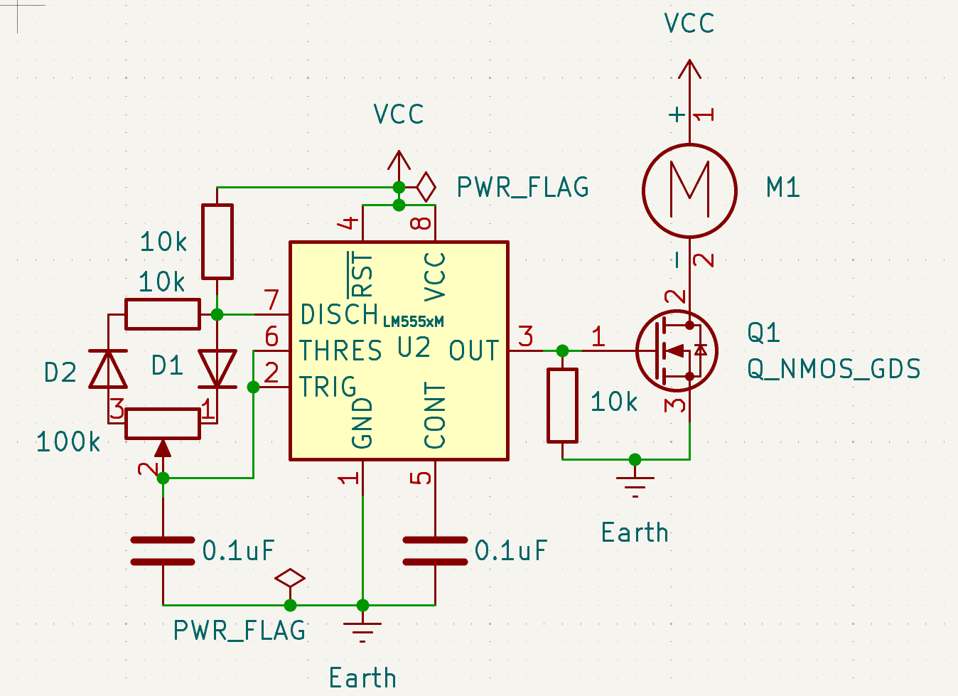
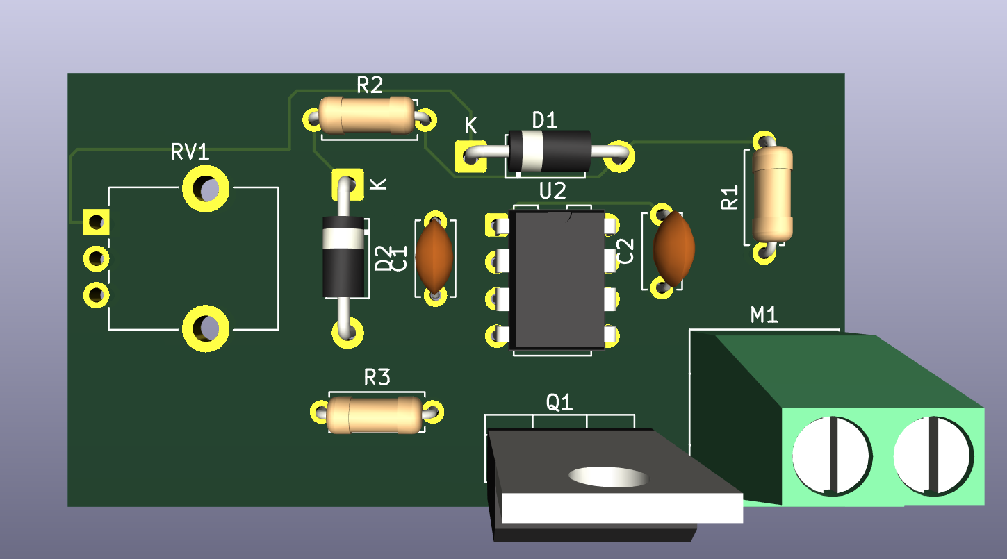
The board layout includes the timer and timing components, a potentiometer footprint, a MOSFET footprint, and a two-position screw terminal for the motor connection. Confirm the board's connector assignments and polarity against the schematic and PCB before wiring.
| Reference | Part/value | Role |
|---|---|---|
U2 | LM555xM | Timer/oscillator |
Q1 | N-channel MOSFET (Q_NMOS_GDS symbol) | Low-side motor switch |
M1 | DC motor (Motor_DC schematic symbol) | Switched load |
RV1 | 100 kΩ potentiometer | Timing adjustment |
R1, R2, R3 | 10 kΩ each | Timing and gate-bias network |
D1, D2 | 1N4007 | Timing-network steering diodes |
C1, C2 | 0.1 µF each | Timer capacitors |
The MOSFET symbol is generic; select a specific part only after checking its pinout, gate-drive requirements, voltage rating, current rating, and thermal limits for the intended motor and supply.
555Timer.kicad_pro.This is a prototype design and should be reviewed and bench-tested before use. The included images are visual references; the KiCad schematic and PCB files are the editable design sources.
| Qty | Value | Footprint | References |
|---|---|---|---|
| 3 | 10k | Resistor_THT:R_Axial_DIN0207_L6.3mm_D2.5mm_P7.62mm_Horizontal | R1, R2, R3 |
| 2 | 0.1uF | Capacitor_THT:C_Disc_D5.0mm_W2.5mm_P5.00mm | C1, C2 |
| 2 | 1N4007 | Diode_THT:D_DO-41_SOD81_P10.16mm_Horizontal | D1, D2 |
| 1 | 100k | Potentiometer_THT:Potentiometer_Alpha_RD901F-40-00D_Single_Vertical_CircularHoles | RV1 |
| 1 | LM555xM | Package_DIP:DIP-8_W7.62mm | U2 |
| 1 | Motor_DC | TerminalBlock_Phoenix:TerminalBlock_Phoenix_MKDS-1,5-2_1x02_P5.00mm_Horizontal | M1 |
| 1 | Q_NMOS_GDS | Package_TO_SOT_THT:TO-220-3_Vertical | Q1 |
11 parts. The full list of its parts is on this page, with links to each part's symbol and footprint where PCBKit's library has them.
From the Md-shiraz/555Timer-PCB-Design repository on GitHub, at the commit this page was made from: the board is 555Timer.kicad_pcb and its schematic .history/555Timer.kicad_sch. PCBKit opens the board in the browser, with nothing to install.
Its repository states no licence, so its author keeps all rights: ask Md-shiraz before reusing the design.
google/mozc-devices
Circuit diagrams and firmware source code for Gboard DIY keyboards


FrameworkComputer/ExpansionCards
Reference designs and documentation to create Expansion Cards for the Framework Laptop

hoglet67/RGBtoHDMI
Bare-metal Raspberry Pi project that provides pixel-perfect sampling of Retro Computer RGB/YUV video and conversion to HDMI

hackclub/OnBoard
💡 Join 1,000 teenagers and make your first PCB with a $100 grant!


tardate/LittleArduinoProjects
a collection of "Little Electronic & Arduino Projects", most involving electronics or an Arduino in one way or another!

basilfx/TRADFRI-Hacking
Hacking IKEA TRÅDFRI products, such as light bulbs, window blinds and other accessories.