2 layers29 × 30.8 mm
ARSensors
mcbearfish/Mini-3D-Window-Viewer
If you stumble across this project feel free to use it for educational purposes. If you find errors or have questions about the circuit design or code feel free to reach out.
12 parts
 mcbearfish/Mini-3D-Window-Viewer
If you stumble across this project feel free to use it for educational purposes. If you find errors or have questions about the circuit design or code feel free to reach out.
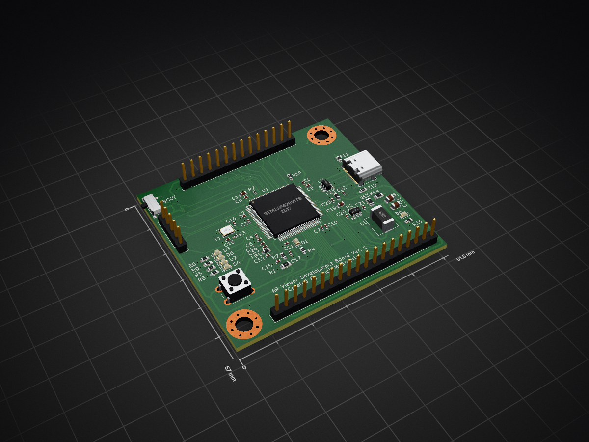
ARviewer is an open-source printed circuit board by mcbearfish, from the mcbearfish/Mini-3D-Window-Viewer repository on GitHub. It is a 2-layer board of 61.5 × 57 mm with 61 parts on 110 nets, routed with 460 tracks and 54 vias.
It is built around the STM32F429VIT6 and USBLC6-2SC6. Its parts include 25 capacitors, 15 resistors, 6 diodes, 4 connectors and 3 ICs. It belongs with the STM32 boards of this library.


This is a developmental project intended to refresh my skills on designing and programming an STM32 microcontroller board. I chose a project scope that I believed would provide difficult circuit and programming challenges. I will document the development process in this README.
If you stumble across this project feel free to use it for educational purposes. If you find errors or have questions about the circuit design or code feel free to reach out. Please cite this repository as a source if you plan to use it.
This project is the 3D Window Viewer.
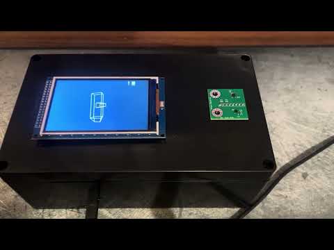
When placed on a flat surface, the device on startup will create a window into a 3D scene of a hammer (Boiler Up and Hail Purdue!). After startup, tilting and rotating the device updates the view of a 3D hammer while the virtual position remains anchored.
This project uses I2C accelerometer, gyroscope, and magnetometer sensors to estimate device orientation in C. The original goal was IMU-only position tracking, but drift made that impractical, so I redesigned the demo around constrained motion.
I designed my own custom STM32 development board and sensor board using KiCad Schematic and PCB Design Software.
This STM32 chip was chosen for its large number of GPIO pins and processing capabilities.
Simple button circuit to test user inputs.
Used for initial testing and debugging.
Provides a highly stable, accurate, and precise frequency reference.
Provides power to the board.
Reset switch.
Grounded pads to use for mounting and probe testing.
Chosen to smooth 5V to 3.3V for STM32 chip and sensors.
Chosen to estimate device orientation and motion. IMU-only position tracking was tested, but drift made it impractical for this version.
Chosen to improve heading estimation and help correct gyro drift over time.
I found Google's Gemini AI tool to be extremely helpful during this design process. Especially with mapping the pinout of the display to STM32. I used a cheap knockoff with no documentation and poor pinout labels. In the future may need to remap pins if display fails to work. See ARSensors project for second Board meant to connect sensors to this main board.
Manufacturing files can be found for each board in this repository.
Designing my first board in almost 4 years was a great experience. In the workspace I have been living in a more software heavy environment. I found this project to be a great refresher of my skills.
I found the initial research phase to be quite enjoyable and straightforward. I easily identified the types of sensors, display, and STM32 chip I thought would be capable for the performance I wanted. Now that I identified the key components it was time to begin creating the schematic.
I quickly realized this was a larger challenge than my senior design project. Although I took a significant part in the circuit design, I realized how beneficial it was having a team of 4 people in multiple disciplines. The components I selected for this project were much more sophisticated than what was chosen for the senior design project. I was honestly a little overwhelmed at the start. I had to take my time and started to break components down. I started with the most important part, the STM32 chip.
For the STM32 I first connected any power related pins and decoupling capacitors. Then I used the STM32CubeMX tool to assign pinouts. I knew between the display and other peripherals I needed a lot of pins, so I started by making sure the chip was capable of supporting them all. Once I verified the chip was capable I began connecting components. The most critical was the USB-C connector, which flashes code onto the chip. The USB-C will also provide power to the whole system. I spent quite a bit of time researching possible power designs. The USB-C provides 5V and I need 3.3V for the STM32 and sensors. I eventually decided on a synchronous buck converter because it would provide an efficient and stable step down from 5V to 3.3V. The display needs 5V, so I decided on a simple low-pass filter because it would provide a clean signal and I have experience with designing those on circuit boards in the past.
Next I added the sensors. I found the datasheets to be extremely helpful. The design process was made much easier by following the typical application circuits that they detailed. Then I added the display, button, and some LEDs. The extra LEDs and button will be useful at the start of programming to make sure the board can properly run code and debug. Lastly I added a connector for debug pins.
Now that I had a schematic to follow I moved onto the PCB layout. This portion was much more difficult than expected. It was at this point I had to take into account physical and cost restrictions. JLCPCB was my choice of board manufacturer. To minimize costs I decided on a 2 layer board, which gave me a lot of physical trace constraints. Also, since the sensors are a bit costly, I decided to move them to a second circuit board to save on future costs. With these new challenges I had to go back to my schematic and STM32CubeMX. Unfortunately I was not able to place my STM32 pinouts more conveniently to minimize trace crossovers. At this point I decided to go with a more generic pin layout that I can wire with some 2.54mm connectors to minimize my trace lengths and crossovers. In the future I will look at more layered boards or other STM32 chips as potential solutions.
To minimize costs on JLCPCB I tried to identify basic parts in the JLCPCB library. Not all parts selected were in that and drove up the cost (~$3 per part not in the basic library). In the future I will place more emphasis on this to lower my costs.
Major credit to Phil's Lab PCB Design video: https://www.youtube.com/watch?v=aVUqaB0IMh4. This was a great refresher on circuit board design and I highly recommend his channel.
When ordering the board I decided that to save on costs to I would hand solder some of the components. This involved things the STM32 chip, USB-C connector, asynchronous buck converter, buttons, and pins. I felt this was a great skill refresher. I took it slow and steady. I started with easier items like the pins and buttons to get back into the flow of things. The picture below is from right before I went to solder the STM chip.
I bought a cheap soldering station and found it pretty useful when adding the smaller components. In the picture below you can see a cheaper soldering iron. I found this ok for the larger components but, I decided it was safer to spend the money and get a proper iron for the delicate items like the USB-C and STM32 chip.
I bought a simple project box and placed the main board inside the box. I left the sensor board on top along with the display to keep them on the same level.
The initial goal of the project was to use the IMU sensors to track the 3D coordinates of the device so that it could act as a camera. The camera would then be able to view a 3D object fixed in space from all angles and get closer or farther away.
While prototyping I found that it was not feasible to use the IMU sensors alone for positional tracking. The significant position drift was too much to overcome, even with adjusting bias in the Kalman filter parameters. I also tested the individual sensors to check for noise and bias. Surprisingly, these cheaper sensors performed quite well. The accelerometer did display the most noise. I believe this was due to environmental sensitivities. Testing was performed on my desk and away from any electronics, this however does not guarantee a perfectly still environment.
Since position is calculated by integrating acceleration twice, even with tiny errors, the positional data errors grew massive. The estimated position drifted so quickly that the 3D object would only remain visible for a split second. I determined this was unusable and decided to change scope.
I decided to pivot the project and try to get the most out of the current setup. I decided to simulate the camera view of the 3D object where moving and tilting the box changes camera view direction realistically, but position is anchored.
The main program initializes the board, sensors, sensor fusion, and 3D engine before entering the main loop. In the loop, new sensor data is read and passed into the sensor fusion algorithm. This project uses an Extended Kalman Filter, which fuses gyroscope, accelerometer, and magnetometer data into a stable orientation estimate. That orientation estimate is then used to update the rendered 3D object and draw the pose overlay.
main()
|
+-- HAL_Init()
+-- SystemClock_Config()
+-- MX_GPIO_Init()
+-- MX_FMC_Init()
+-- I2C_Bus_Reset()
+-- MX_I2C1_Init()
|
+-- Engine3D_Init()
|   \-- GPU_Init()
|
+-- Sensors_Init()
+-- Sensors_ShowStartupCountdown()
+-- Sensors_Calibrate()
+-- Sensors_ShowInstructionScreen()
+-- Sensors_GetReferenceFrame()
+-- EKF_Init()
+-- EKF_SetReference()
|
\-- while (1)
    +-- Sensors_Read()
    +-- EKF_Predict()
+-- EKF_Update()Portions of the firmware were developed with assistance from AI tools, including OpenAI Codex and Google's Gemini. I used these tools to help generate code structure, debug embedded issues and tune parts of the sensor-fusion pipeline. All AI-assisted code was reviewed, tested, and modified by me before being included in the final project.
I found Codex especially useful for working through embedded C issues and code organization. Gemini was useful during early design exploration, especially for brainstorming and pin-mapping support, but I had to review its output carefully because it sometimes suggested larger code changes than intended.
The final device renders a wireframe 3D hammer on the LCD. After startup calibration, tilting or rotating the physical box updates the rendered view in real time. The device uses IMU sensor fusion for orientation estimation while keeping virtual position constrained to avoid IMU drift.
This project was great for refreshing my bare-metal embedded skills. Making a device and writing code that brings it to life is always a joy. The next project should hopefully move faster now that I have regained familiarity with the whole process.
| Qty | Value | Footprint | References |
|---|---|---|---|
| 13 | 100n | Capacitor_SMD:C_0402_1005Metric | C2, C3, C4, C5, C6, C8, C10, C11, C15, C17, C20, C22, C23 |
| 6 | 1k5 | Resistor_SMD:R_0603_1608Metric | R4, R5, R6, R8, R9, R15 |
| 2 | 10u | Capacitor_SMD:C_0603_1608Metric | C1, C19 |
| 2 | 120R | Inductor_SMD:L_0603_1608Metric | FB1, FB2 |
| 2 | 14pF | Capacitor_SMD:C_0402_1005Metric | C16, C18 |
| 2 | 1u | Capacitor_SMD:C_0402_1005Metric | C13, C14 |
| 2 | 22u | Capacitor_SMD:C_0805_2012Metric | C24, C25 |
| 2 | 2u2 | Capacitor_SMD:C_0402_1005Metric | C7, C9 |
| 2 | 5k1 | Resistor_SMD:R_0603_1608Metric | R11, R12 |
| 2 | GREEN | LED_SMD:LED_0603_1608Metric | D1, D6 |
| 2 | MountingHole_Pad | MountingHole:MountingHole_4.3mm_M4_Pad_Via | H1, H2 |
| 1 | 100k | Resistor_SMD:R_0805_2012Metric | R1 |
| 1 | 10k | Resistor_SMD:R_0805_2012Metric | R14 |
| 1 | 10k | Resistor_SMD:R_0402_1005Metric | R7 |
| 1 | 10n | Capacitor_SMD:C_0402_1005Metric | C12 |
| 1 | 10p | Capacitor_SMD:C_0402_1005Metric | C21 |
| 1 | 1k | Resistor_SMD:R_0603_1608Metric | R2 |
| 1 | 22 | Resistor_SMD:R_0603_1608Metric | R10 |
| 1 | 25MHz | Crystal:Crystal_SMD_3225-4Pin_3.2x2.5mm | Y1 |
| 1 | 3.3u | Inductor_SMD:L_6.3x6.3_H3 | L1 |
| 1 | 33k2 | Resistor_SMD:R_0805_2012Metric | R13 |
| 1 | 450 | Resistor_SMD:R_0402_1005Metric | R3 |
| 1 | AP62300TWU-7 | Package_TO_SOT_SMD:TSOT-23-6 | U2 |
| 1 | BLUE | LED_SMD:LED_0603_1608Metric | D3 |
| 1 | Conn_01x05 | Connector_PinHeader_2.54mm:PinHeader_1x05_P2.54mm_Vertical | J4 |
| 1 | Conn_01x14 | Connector_PinHeader_2.54mm:PinHeader_1x14_P2.54mm_Vertical | J1 |
| 1 | Conn_01x19 | Connector_PinHeader_2.54mm:PinHeader_1x19_P2.54mm_Vertical | J3 |
| 1 | ORANGE | LED_SMD:LED_0603_1608Metric | D2 |
| 1 | RED | LED_SMD:LED_0603_1608Metric | D5 |
| 1 | STM32F429VIT6 | Package_QFP:LQFP-100_14x14mm_P0.5mm | U1 |
| 1 | SW_Push | Button_Switch_THT:SW_PUSH_6mm | SW1 |
| 1 | SW_SPDT | Button_Switch_SMD:SW_SPDT_PCM12 | SW2 |
| 1 | USBLC6-2SC6 | Package_TO_SOT_SMD:SOT-23-6 | U3 |
| 1 | USB_C_Receptacle_USB2.0_16P | Connector_USB:USB_C_Receptacle_GCT_USB4105-xx-A_16P_TopMnt_Horizontal | J2 |
| 1 | YELLOW | LED_SMD:LED_0603_1608Metric | D4 |
mcbearfish/Mini-3D-Window-Viewer
If you stumble across this project feel free to use it for educational purposes. If you find errors or have questions about the circuit design or code feel free to reach out.


TalismanDesign/PocketMage_PDA
An E-Ink PDA device using the ESP32 S3.


shorepine/tulipcc
The Tulip Creative Computer and AMYboard - portable Python synthesizers


LeoDJ/FW-EC-DongleHiderPlus
Framework Expansion Card that includes a USB hub to hide a bare dongle inside and still have a USB-A port externally
It measures 61.5 × 57 mm and has 2 copper layers, 1.6 mm thick.
61 parts, built around the STM32F429VIT6 and USBLC6-2SC6. The full list of its parts is on this page, with links to each part's symbol and footprint where PCBKit's library has them.
From the mcbearfish/Mini-3D-Window-Viewer repository on GitHub, at the commit this page was made from: the board is ARviewer/ARviewer.kicad_pcb and its schematic ARSensors/ARSensors.kicad_sch. PCBKit opens the board in the browser, with nothing to install.
Its repository states no licence, so its author keeps all rights: ask mcbearfish before reusing the design.