
2 layers51.4 × 39.9 mm

 mbtech-nl/majestouch-stm322
Drop-in replacement controller for the full-size Filco Majestouch: STM32F072, QMK with NKRO over USB. KiCad 9 board, hand-solderable.
Majestouch stm32 is an open-source printed circuit board by mbtech-nl, from the mbtech-nl/majestouch-stm32 repository on GitHub, published under the MIT licence. It is a 2-layer board of 50 × 18 mm with 20 parts on 51 nets, routed with 209 tracks and 23 vias.
It is built around the STM32F072CBT6, AP2112K-3.3 and USBLC6-2SC6. Its parts include 9 capacitors, 4 resistors, 4 connectors and 3 ICs. It belongs with the keyboards and input boards and the STM32 boards of this library.


A drop-in replacement controller for the full-size Filco Majestouch, built around an STM32F072. It replaces the stock daughterboard, plugs into the same 36-pin header on the main PCB and runs QMK; the QMK keyboard definition is included.
Download: the latest release
has everything needed to build the controller: the Gerber package to order the board from
any PCB fab, the parts list (BOM) and the ready-built QMK firmware (.bin).
See Making one for how to order, assemble and flash it.
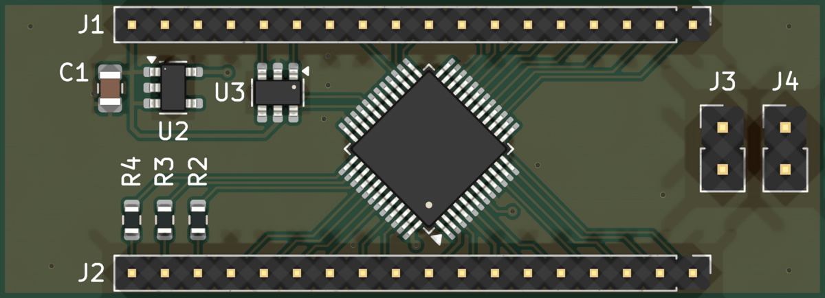
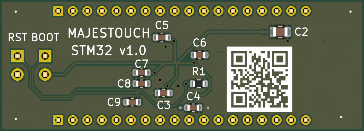
Component side (faces the main PCB) and outward side, rendered from the KiCad board.
My 2010 Majestouch was getting on, so I went looking for a replacement. Nothing on offer today quite suited my taste, and every switch still worked. Maybe a good clean and a fresh set of keycaps would hold me over for the next 15 years?
Still, all those modern keyboards did NKRO over USB, and that reminded me: mine used to do NKRO too, back when it was plugged in over PS/2. PS/2 left my desk a long time ago, and over USB the stock controller only does 6KRO. Reading up on it, I came across the Kitten Paw (ATmega32U2 + 74HC154), the replacement controller for Costar boards such as the Filco, about a decade after everyone else did. I also found Majestouch-2-TKL-Replacement-Controller, which does the same for the Majestouch 2 TKL with an STM32.
So I designed my own replacement controller, taking that STM32 approach to the full-size board. It's my first open source hardware project, and the design turned out to be quite straightforward. Did I need NKRO? Honestly, I never noticed it was missing. Am I happy with the result? Definitely.
The board keeps it simple:
Built for and measured on a full-size ANSI Majestouch with main PCB
CST 104/5/6 Main PCBA Rev 1.2 and stock daughterboard
CST-DAUGHTER PCBA Rev 3.1 ESD.
The full-size Filcos below share the same 36-pin header and matrix according to deskthority, and the Kitten Paw is listed for the same main PCBs, so they are expected to work, but are untested with this board:
| Keyboard | Main PCB |
|---|---|
| Majestouch (FKBN104/105) | CST-FKB/N-104/5/6 Main PCBA Rev 1.0 / 1.2 (2010) |
| Majestouch Linear R | CST-F104/5/6/8 Main PCB Rev 2.1 (2010) |
| Majestouch 2 | CST-F104/5/6/8 Main PCB Rev 3.0 (2012) |
Full NKRO needs a diode per key. Filco marks those boards with an N in the model code (FKBN…, "N-key rollover using separate diodes"); the cheaper 2KRO models without it work too, but ghost on some key combinations.
Compare your stock controller with the pinout below before fitting. The QMK definition has the ANSI layout; ISO boards work electrically, but the two extra ISO keys need a layout of your own. The Majestouch TKL uses a different header and does not fit.
kicad/                       KiCad 9 project (schematic, board, design rules)
firmware/majestouch_stm32/   QMK keyboard definition
tools/check.py               validation: schematic, firmware pins and board
tools/fab.py                 fabrication package (Gerbers, drill, BOM)
docs/                        board renders, photos of the stock controller
tools/check.py checks the schematic against the STM32 datasheet pinout and
the Filco header map, checks that every pin in the QMK definition lands on the
right net, and runs KiCad's design rule check on the board. It needs KiCad 9
(kicad-cli and the pcbnew Python module).
From the Filco Majestouch table on deskthority's controller matrix traces page, cross-checked pin for pin against the Kitten Paw schematic. The component side faces the main PCB; seen from that side, pin 1 is top-right, pins 1–18 run right to left, and pin 19 sits directly below pin 1.
| Pin | Signal | STM32 | Pin | Signal | STM32 | |
|---|---|---|---|---|---|---|
| 1 | COL0 | PA5 | 19 | ROW_K | PA3 | |
| 2 | ROW_A | PA6 | 20 | COL1 | PA2 | |
| 3 | ROW_B | PA7 | 21 | ROW_L | PA1 | |
| 4 | ROW_C | PB0 | 22 | COL2 | PA0 | |
| 5 | ROW_D | PB1 | 23 | COL3 | PF1 | |
| 6 | ROW_E | PB2 | 24 | ROW_M | PF0 | |
| 7 | ROW_F | PB10 | 25 | ROW_N | PC15 | |
| 8 | ROW_G | PB11 | 26 | ROW_O | PC14 | |
| 9 | ROW_H | PB12 | 27 | ROW_P | PC13 | |
| 10 | ROW_I | PB13 | 28 | ROW_Q | PB9 | |
| 11 | ROW_J | PB14 | 29 | COL4 | PB8 | |
| 12 | GND | 30 | ROW_R | PB7 | ||
| 13 | USB D+ | ESD → PA12 | 31 | COL5 | PB6 | |
| 14 | USB D− | ESD → PA11 | 32 | COL6 | PB5 | |
| 15 | n/c | 33 | COL7 | PB4 | ||
| 16 | n/c | 34 | LED Num Lock | PB3 | ||
| 17 | n/c | 35 | LED Caps Lock | PA15 | ||
| 18 | VBUS | LDO in | 36 | LED Scroll Lock | PA14 |
Pins 15 and 16 are tied to GND on the main PCB; this board leaves 15–17 unconnected.
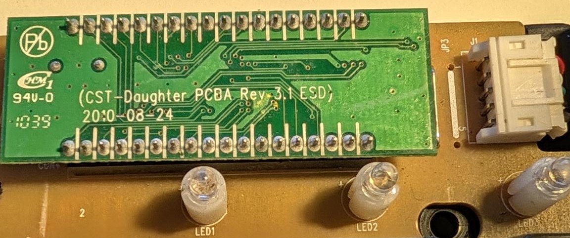
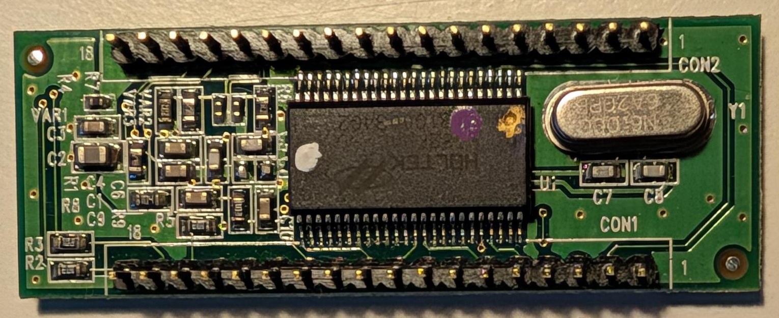
The stock controller this board replaces: installed, solder side up, next to the lock LEDs and the USB cable connector; and removed, component side, oriented like the render above (CON2 = pins 1–18 on top, pin 1 at the right).
COL2ROW). The main PCB
has no pull-ups to 5 V on the matrix lines, so the 3.6 V-only pins
(PA0–PA7, PB0/PB1) are safe.Board: 50 × 18 mm, 2 layers, 1.2 mm FR-4. 0.15 mm tracks and clearance (0.25 mm for power), 0.3 mm vias, GND pour on both sides. The MCU sits at 45° so each side fans out to one header row. ICs, C1 and the LED resistors are on the component side (facing the main PCB), the other passives on the outward side. The outward side carries the reference designators, BOOT/RST labels and a QR code linking to this repository.
cd tools
python3 check.py   # validate first
python3 fab.py
This builds kicad/fab/majestouch_stm32-gerbers-<rev>.zip (Gerbers and drill
files, accepted by any PCB fab) plus bom.csv with the parts used and what an
equivalent needs. Tagged releases have both attached, together with the QMK
firmware, built and validated by GitHub Actions
(.github/workflows/release.yml).
Order settings: 2 layers, FR-4, 1.2 mm (the stock board's thickness; 1.6 mm
fits too), HASL lead-free or ENIG. The design stays within standard rules
(0.15 mm track/space, 0.3 mm drills). If your fab prints an order number on
the board (JLCPCB does by default), choose the option without it, so it
doesn't land on the QR code. cpl.csv (pick-and-place) is only needed if the
fab assembles the board.
| Ref | Part | Package |
|---|---|---|
| U1 | STM32F072CBT6 | LQFP-48 |
| U2 | AP2112K-3.3 | SOT-23-5 |
| U3 | USBLC6-2SC6 | SOT-23-6 |
| C1 | 4.7 µF | 0805 |
| C2 | 10 µF | 0805 |
| C3–C6, C9 | 100 nF | 0603 |
| C7 | 1 µF | 0603 |
| C8 | 10 nF | 0603 |
| R1–R4 | 10 k | 0603 |
| J1, J2 | 2.0 mm pin header, 1 × 40 strip snapped to 2 × 18 | |
| J3, J4 | 2.54 mm 1 × 2 header (optional) |
Any equivalent part works: X5R/X7R capacitors at 10 V or more, 1 % or 5 % resistors.
U1, U2, U3, C1 and R2–R4 go on the component side, the other passives on the back; every part is labelled on the silkscreen. Mind the pin-1 triangles on U1, U2 and U3: U2 and U3 short VBUS to GND when rotated. Solder the pin headers last, with the plastic on the component side, then fit the board in place of the stock controller.
Each release has a ready-built majestouch_stm32-qmk-<version>.bin with the
default keymap; the release notes name the QMK version it was built with. To
build it yourself, copy firmware/majestouch_stm32 into
qmk_firmware/keyboards/, then:
qmk compile -kb majestouch_stm32 -km defaultFirst flash: bridge the BOOT jumper while plugging in USB (or bridge BOOT and
tap RESET) to start the STM32's DFU bootloader, then
qmk flash -kb majestouch_stm32 -km default, or for the release binary
dfu-util -a 0 -d 0483:df11 -s 0x08000000:leave -D majestouch_stm32-qmk-<version>.bin.
After that, hold Esc while plugging in to get back to the bootloader.
The default keymap is a standard full-size ANSI layout. The Caps/Num/Scroll LEDs follow the host's lock state.
Measured on the target keyboard before ordering:
Tested with the first board built from these files, in the same keyboard:
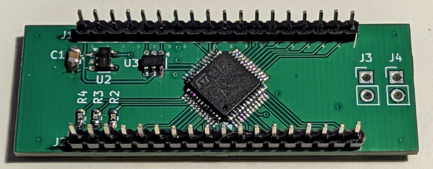
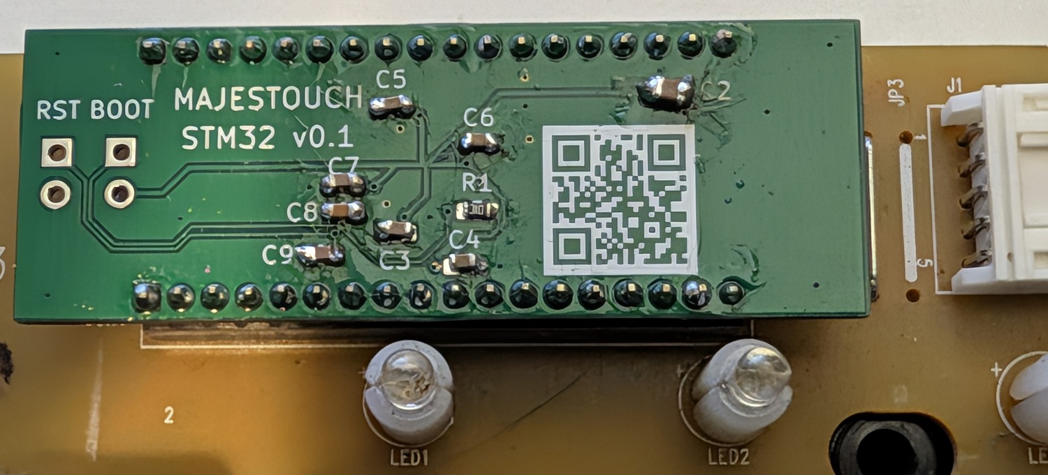
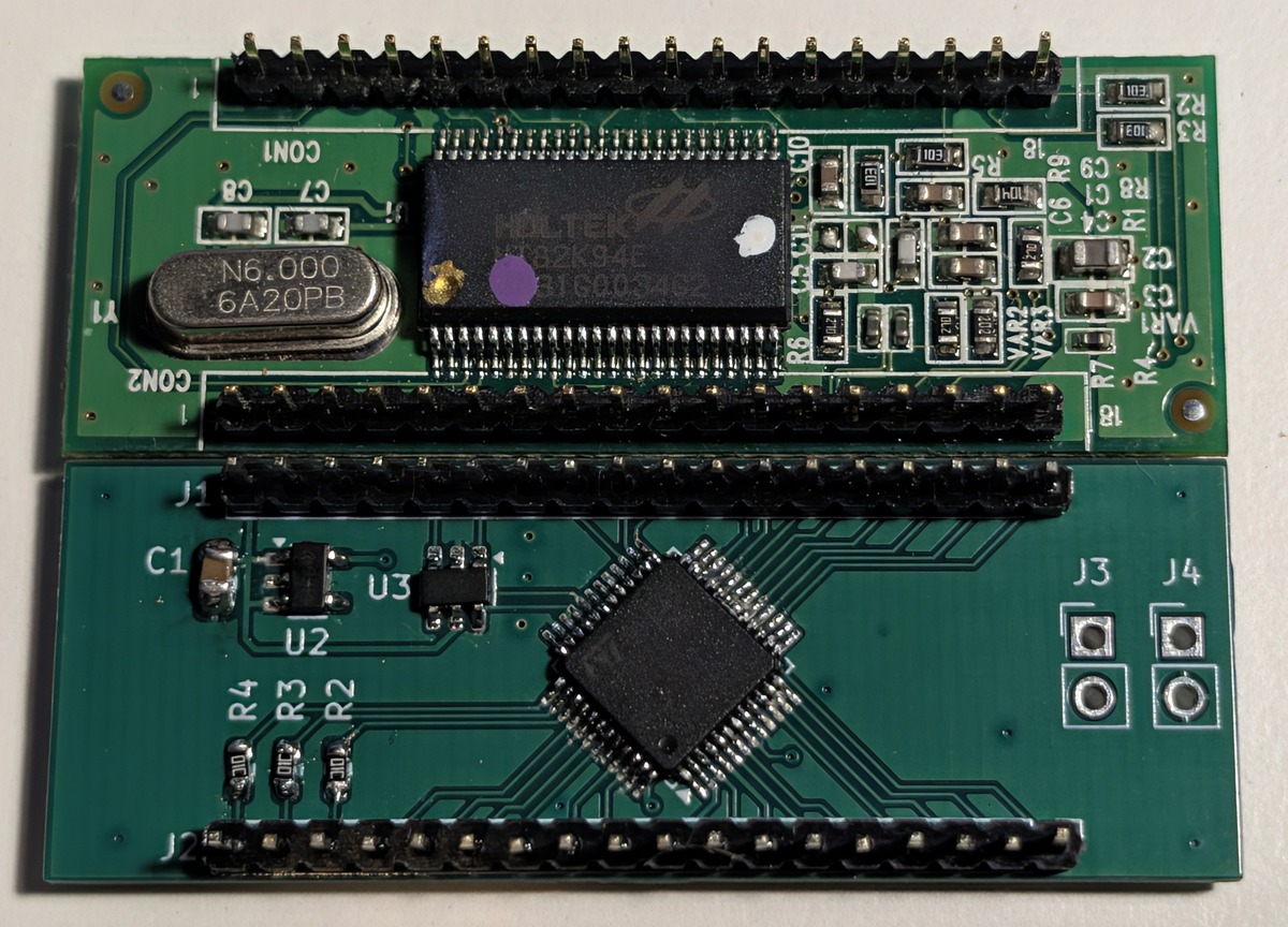
The first board: assembled, installed in place of the stock controller (oriented like the photo of the stock one above), and next to the stock controller it replaces. Forgive the prototype-quality soldering.
MIT, see LICENSE. This covers the hardware, the tools and the QMK keyboard definition. Firmware built with QMK includes QMK itself, which is GPL-2.0-or-later, so compiled binaries fall under the GPL.
| Qty | Value | Footprint | References |
|---|---|---|---|
| 5 | 100nF | Capacitor_SMD:C_0603_1608Metric | C3, C4, C5, C6, C9 |
| 4 | 10k | Resistor_SMD:R_0603_1608Metric | R1, R2, R3, R4 |
| 1 | 10nF | Capacitor_SMD:C_0603_1608Metric | C8 |
| 1 | 10uF | Capacitor_SMD:C_0805_2012Metric | C2 |
| 1 | 1uF | Capacitor_SMD:C_0603_1608Metric | C7 |
| 1 | 4.7uF | Capacitor_SMD:C_0805_2012Metric | C1 |
| 1 | AP2112K-3.3 | Package_TO_SOT_SMD:SOT-23-5 | U2 |
| 1 | BOOT | Connector_PinHeader_2.54mm:PinHeader_1x02_P2.54mm_Vertical | J3 |
| 1 | Filco 1-18 | Connector_PinHeader_2.00mm:PinHeader_1x18_P2.00mm_Vertical | J1 |
| 1 | Filco 19-36 | Connector_PinHeader_2.00mm:PinHeader_1x18_P2.00mm_Vertical | J2 |
| 1 | RESET | Connector_PinHeader_2.54mm:PinHeader_1x02_P2.54mm_Vertical | J4 |
| 1 | STM32F072CBT6 | Package_QFP:LQFP-48_7x7mm_P0.5mm | U1 |
| 1 | USBLC6-2SC6 | Package_TO_SOT_SMD:SOT-23-6 | U3 |


nuess0r/ctrl-M
Replacement controller for the famous IBM Model M keyboard based on the STM32F072 microcontroller. Supported by QMK.

vuckale/takt11800
Replacement PCB for Cherry G80 11800/Compaq MX 11800 keyboard using QMK firmware and VIA


slemanz/chronolog
STM32-based temperature data logger with RTC, NOR flash storage, LCD and Wi-Fi. Hardware and firmware.
It measures 50 × 18 mm and has 2 copper layers, 1.6 mm thick.
20 parts, built around the STM32F072CBT6, AP2112K-3.3 and USBLC6-2SC6. The full list of its parts is on this page, with links to each part's symbol and footprint where PCBKit's library has them.
From the mbtech-nl/majestouch-stm32 repository on GitHub, at the commit this page was made from: the board is kicad/majestouch_stm32.kicad_pcb and its schematic kicad/majestouch_stm32.kicad_sch. PCBKit opens the board in the browser, with nothing to install.
Its repository publishes it under the MIT licence: you may reuse it on that licence's terms (keep the author's notice, and for a copyleft licence share your changes alike).