2 layers240 × 194 mm
Infinitas
freeDSP/freeDSP-INFINITAS
USB Audio Class 2 compliant audio interface with up to 32 input and up to 32 output channels and optional ADAU1452 DSP.
1,020 parts35
 mbayrao/YMC-Mathpad
這款鍵盤靈感來自Summa-Congni/Mathpad,當我在2025年的某日給女朋友看到能夠方便輸入數學符號的Mathpad 她知道我喜歡也能製做出電路板,便鼓勵我著手製作此project而誕生。 此板為第一版設計,製作時有許多問題導致設計不斷變更直到最後。 主要思路為無線藍芽連接內置5V USB Type C充電電路並提供電量指示燈、有OLED螢幕可供視覺回饋挑選符號
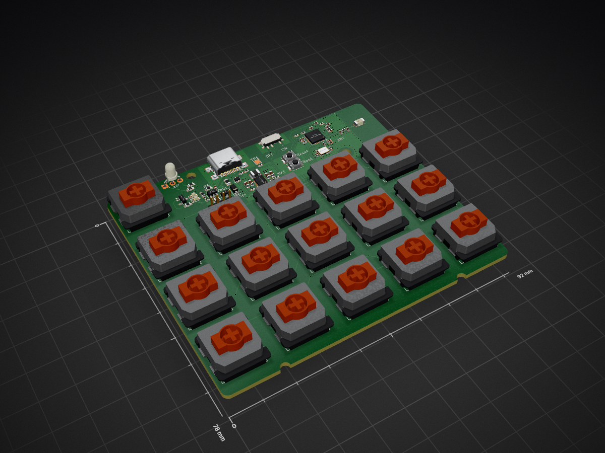
Mathpad is an open-source printed circuit board by mbayrao, from the mbayrao/YMC-Mathpad repository on GitHub. It is a 4-layer board of 92 × 78 mm with 93 parts on 76 nets, routed with 522 tracks and 229 vias.
It is built around the ESP32-C3FH4, RT6154AGQW and TP4054, with the USBLC6-2P6, 1N5817WS and ANT3216LL00R2400A among its other parts. Its parts include 20 capacitors, 19 switches, 18 diodes, 17 resistors and 4 ICs. It belongs with the ESP32 and RISC-V boards of this library.


這是我第一次用Git…有好多操作要學…Work on it...
這款鍵盤靈感來自Summa-Congni/Mathpad,當我在2025年的某日給女朋友看到能夠方便輸入數學符號的Mathpad 她知道我喜歡也能製做出電路板,便鼓勵我著手製作此project而誕生。 此板為第一版設計,製作時有許多問題導致設計不斷變更直到最後。 主要思路為無線藍芽連接內置5V USB Type C充電電路並提供電量指示燈、有OLED螢幕可供視覺回饋挑選符號
使用Gateron Low Profile THT軸體搭配白色矮鍵, 0.96吋雙色I2C OLED螢幕顯示現在電量、數學符號及實際發送文字
數學符號
Layer1: ±×÷…≤≥≠√∑∏∞αβγ
Layer2: δεμφπσθ∈∉∫∂∆∇≈
Layer3: ≅≡∪∩≃≄∨∧∴∵⊆⊇⊂⊃
Layer4: ⊗⊕⊙∀∃ℕℤℚℝℍℙρ⇒⇔
此 Repository 包含自行製作一把鍵盤所需的所有檔案:
| Folder | Contents |
|---|---|
/hardware/pcb | KiCad/Eagle 電路圖、PCB 佈局、Gerber 製造檔、BOM |
/hardware/cad | CAD 原始檔(STEP)、外殼/定位板 STEP 輸出檔 |
/firmware | 韌體原始碼 |
/hardware/pcb/gerbers 中的 Gerber 製造檔,向 [JLCPCB/PCBWay/其他] 下單製作。/hardware/cad 中的 STEP 檔進行 3D 列印或 CNC 加工。hardware/cad/完整電路圖 PDF:hardware/pcb/YMC_Mathpad_v1.pdf
本專案受到 Mathpad(作者:[nup002\dancergraham])的啟發,並以其為基礎進行開發。
本專案為業餘/開源專案,以「現況」提供,不提供任何保固。下單或焊接前,請確認所有元件的規格與額定值符合需求。
| Qty | Value | Footprint | References |
|---|---|---|---|
| 16 | 1N5817WS | Diode_SMD:D_SOD-123 | D3, D4, D5, D6, D7, D8, D9, D10, D11, D12, D13, D14, D15, D16, D17, D18 |
| 16 | SW_Push | key-switches.pretty-main:SW_Gateron_LowProfile_THT | SW1, SW2, SW3, SW4, SW5, SW6, SW7, SW8, SW9, SW10, SW11, SW12, SW13, SW14, SW15, SW16 |
| 6 | 10k | Resistor_SMD:R_0402_1005Metric | R11, R12, R13, R16, R17, R19 |
| 5 | 100n | Capacitor_SMD:C_0402_1005Metric | C22, C24, C25, C26, C28 |
| 4 | 47uF X5R | Capacitor_SMD:C_0603_1608Metric | C10, C11, C13, C16 |
| 2 | 100R | Resistor_SMD:R_0603_1608Metric | R14, R15 |
| 2 | 100k 1% | Resistor_SMD:R_0402_1005Metric | R3, R4 |
| 2 | 100nF | Capacitor_SMD:C_0402_1005Metric | C14, C20 |
| 2 | 13pF | Capacitor_SMD:C_0402_1005Metric | C8, C9 |
| 2 | 1uF | Capacitor_SMD:C_0402_1005Metric | C21, C27 |
| 2 | 3.3pF | Capacitor_SMD:C_0402_1005Metric | C17, C18 |
| 2 | 5.1k 1% | Resistor_SMD:R_0402_1005Metric | R10, R18 |
| 2 | Boot | Button_Switch_SMD:SW_Push_SPST_NO_Alps_SKRK | SW17, SW18 |
| 1 | 100k_0402_1% | Resistor_SMD:R_0402_1005Metric | R2 |
| 1 | 10u | Capacitor_SMD:C_0402_1005Metric | C23 |
| 1 | 10uF | Capacitor_SMD:C_0603_1608Metric | C15 |
| 1 | 1A | Fuse:Fuse_0805_2012Metric | F1 |
| 1 | 1uF_0402 | Capacitor_SMD:C_0402_1005Metric | C12 |
| 1 | 2.2nH | Inductor_SMD:L_0402_1005Metric | L3 |
| 1 | 2.2uH 3A | Inductor_SMD:L_1008_2520Metric | L2 |
| 1 | 24nH | Inductor_SMD:L_0402_1005Metric | L1 |
| 1 | 2nH | Inductor_SMD:L_0402_1005Metric | L4 |
| 1 | 3.3k_0603_1% | Resistor_SMD:R_0603_1608Metric | R5 |
| 1 | 40MHz | Crystal:Crystal_SMD_3225-4Pin_3.2x2.5mm | Y1 |
| 1 | 560k_0402_1% | Resistor_SMD:R_0402_1005Metric | R1 |
| 1 | 680_0603 | Resistor_SMD:R_0603_1608Metric | R9 |
| 1 | 68k_0603 | Resistor_SMD:R_0603_1608Metric | R6 |
| 1 | ANT3216LL00R2400A | SamacSys_Parts:ANT3216LL00R2400A | ANT1 |
| 1 | AO3401A | Package_TO_SOT_SMD:SOT-23 | Q1 |
| 1 | BATT | Connector_JST:JST_ZH_S2B-ZR-SM4A-TF_1x02-1MP_P1.50mm_Horizontal | J3 |
| 1 | COM | Connector_PinHeader_2.00mm:PinHeader_1x04_P2.00mm_Vertical | J2 |
| 1 | ESP32-C3FH4 | Package_DFN_QFN:QFN-32-1EP_5x5mm_P0.5mm_EP3.7x3.7mm | U2 |
| 1 | Green | LED_SMD:LED_0603_1608Metric | DP2 |
| 1 | LED_Dual_AKA | LED_THT:LED_D3.0mm-3 | D2 |
| 1 | MBR120VLSFT | Diode_SMD:D_SOD-123 | D1 |
| 1 | MMBT2222A | Package_TO_SOT_SMD:SOT-23 | Q31 |
| 1 | MSK12C02 | SamacSys_Parts:MSK12C02 | S1 |
| 1 | RT6154AGQW | SamacSys_Parts:SON50P300X400X80-15N-D | IC1 |
| 1 | Red | LED_SMD:LED_0603_1608Metric | DP1 |
| 1 | TP4054 | Package_TO_SOT_SMD:SOT-23-5 | IC2 |
| 1 | TestPoint | TestPoint:TestPoint_Pad_1.5x1.5mm | TP1 |
| 1 | USBLC6-2P6 | Package_TO_SOT_SMD:SOT-666 | U1 |
| 1 | USB_C_Receptacle_USB2.0_16P | Connector_USB:USB_C_Receptacle_GCT_USB4110 | J1 |
freeDSP/freeDSP-INFINITAS
USB Audio Class 2 compliant audio interface with up to 32 input and up to 32 output channels and optional ADAU1452 DSP.

zeankundev/boards
A collection and an archive of KiCad projects I made. Contains projects from 2023 - 2024.

akionu/mameTDT
$\theta=−5.3 × 10^{−2} + 2.92 × 10^{−2} \epsilon−5.5 × 10^{−4} \epsilon^2+ 4.3 × 10^{−6}\epsilon^3$ ただし、土の水分量$\theta [m^3/m^3]$、比誘電率$\epsilon$です。


sabogalc/project-piCo
Because it should be a crime to release a product with Micro-USB in the 2020s

lightsource-nz/crossfire
MCU application to route MIDI message streams between USB-based MIDI devices

RoyZeng0317/kicad
This is the kicad circuit diagram layout, it's have more layout in here.

It measures 92 × 78 mm and has 4 copper layers, 1.6 mm thick.
93 parts, built around the ESP32-C3FH4, RT6154AGQW, TP4054 and USBLC6-2P6. The full list of its parts is on this page, with links to each part's symbol and footprint where PCBKit's library has them.
From the mbayrao/YMC-Mathpad repository on GitHub, at the commit this page was made from: the board is Hardware/Kicad/Mathpad.kicad_pcb and its schematic Hardware/Kicad/BlockDiagram.kicad_sch. PCBKit opens the board in the browser, with nothing to install.
Its repository states no licence, so its author keeps all rights: ask mbayrao before reusing the design.