
2 layers146.2 × 99 mm
FPVRover
Circuit-Digest/ESP32-Cam-Surveillance-Car
Watch full video on ESP32 surveillance car
35 parts15

 MayankBagad/Electabuzz_Unplugged
Submission for Unplugged round 2 by Team Electabuzz
Team electrabuzz is an open-source printed circuit board by MayankBagad, from the MayankBagad/Electabuzz_Unplugged repository on GitHub. It is a 2-layer board of 167.1 × 181.2 mm with 11 parts on 66 nets, routed with 157 tracks and 12 vias.
It is built around the ESP32-CAM, LM2596S-5.0 and TSSP58038, with the TP4056 among its other parts. It belongs with the ESP32 and RISC-V boards of this library.


A custom hardware design, PCB layout, sensor interface, and power system package for a line-following mobile robot platform.
Developed by Team Electrabuzz for UNPLUGGED — A 24-Hour Hardware Hackathon organized by DJSCE × IETE-ISF × DJS MicroMinds VLSI Club.


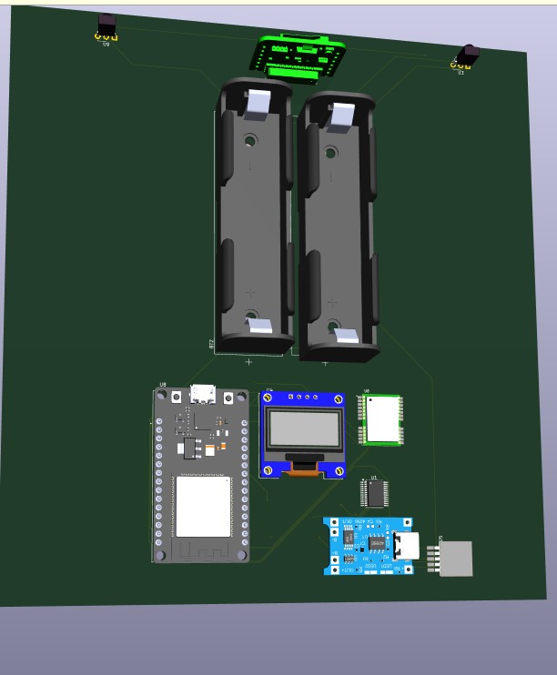
Line-follower robots require clean sensor signal routing, reliable motor current delivery, and stable logic power. Connecting high-draw DC motors directly to the same unregulated battery rail as the microcontroller often causes voltage dips, electrical noise, and unwanted MCU resets.
Electabuzz addresses these requirements at the board level:
                              ┌───────────────────┐
                              │  6V Solar Panel   │
                              └─────────┬─────────┘
                                        │ (1N5819 Schottky Diode)
                                        ▼
 ┌──────────────────────┐     ┌───────────────────┐
 │ 2× 18650 Li-ion      │◄───►│  TP4056 Charger   │
 │ Battery (Parallel)   │     │ (Protection IC)   │
 └──────────────────────┘     └─────────┬─────────┘
                                        │ ~3.7V - 4.2V VBAT
                                        ▼
                              ┌───────────────────┐
                              │ LM2596 Buck Conv. │──► 5.0V Logic Rail (ESP32 VIN, CAM 5V)
                              └─────────┬─────────┘
                                        │
           ┌────────────────────────────┴────────────────────────────┐
           │                                                         │
           ▼                                                         ▼
 ┌───────────────────┐                                     ┌───────────────────┐
 │ ESP32-DEVKIT-V1   │◄────────────── UART0 ──────────────►│ ESP32-CAM (OV2640)│
 │ (Main Controller) │                                     └───────────────────┘
 └───┬───┬───┬───┬───┘
     │   │   │   │
│ │ │ └─────────── I²C (GPIO 21/22) ───────────► 0.96" SSD1306 OLED (0x3C)| ESP32 Pin | Connected Device | Pin / Function | Signal Type | Description |
|---|---|---|---|---|
| GPIO 25 | TB6612FNG | AIN1 | Digital Out | Motor A Direction 1 |
| GPIO 26 | TB6612FNG | AIN2 | Digital Out | Motor A Direction 2 |
| GPIO 27 | TB6612FNG | PWMA | PWM Out | Motor A Speed Control |
| GPIO 14 | TB6612FNG | BIN1 | Digital Out | Motor B Direction 1 |
| GPIO 12 | TB6612FNG | BIN2 | Digital Out | Motor B Direction 2 |
| GPIO 13 | TB6612FNG | PWMB | PWM Out | Motor B Speed Control |
| GPIO 32 | TB6612FNG | STBY | Digital Out | Driver Enable / Standby ($10\text{ k}\Omega$ pull-up) |
| GPIO 21 | SSD1306 OLED | SDA | I²C Data | Display I²C Data line ($4.7\text{ k}\Omega$ pull-up) |
| GPIO 22 | SSD1306 OLED | SCL | I²C Clock | Display I²C Clock line ($4.7\text{ k}\Omega$ pull-up) |
| GPIO 16 | NEO-6M GPS | TX | UART RX2 | Serial GPS telemetry input |
| GPIO 17 | NEO-6M GPS | RX | UART TX2 | Serial configuration output |
| GPIO 34 | IR Sensor 1 | OUT | Digital In | Leftmost line sensor |
| GPIO 35 | IR Sensor 2 | OUT | Digital In | Mid-left line sensor |
| GPIO 36 | IR Sensor 3 | OUT | Digital In | Center line sensor |
| GPIO 39 | IR Sensor 4 | OUT | Digital In | Mid-right line sensor |
| GPIO 33 | IR Sensor 5 | OUT | Digital In | Rightmost line sensor |
| GPIO 1 | ESP32-CAM | U0RXD | UART TX0 | Inter-module serial link |
| GPIO 3 | ESP32-CAM | U0TXD | UART RX0 | Inter-module serial link |
📖 Full Details: For bus specifications and pinout notes, see Architecture Documentation.
| Schematic Capture | Copper Layer Routing (Top & Bottom) |
|---|---|
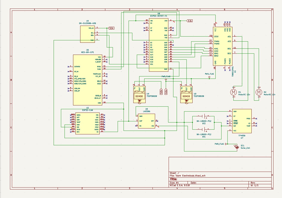 | 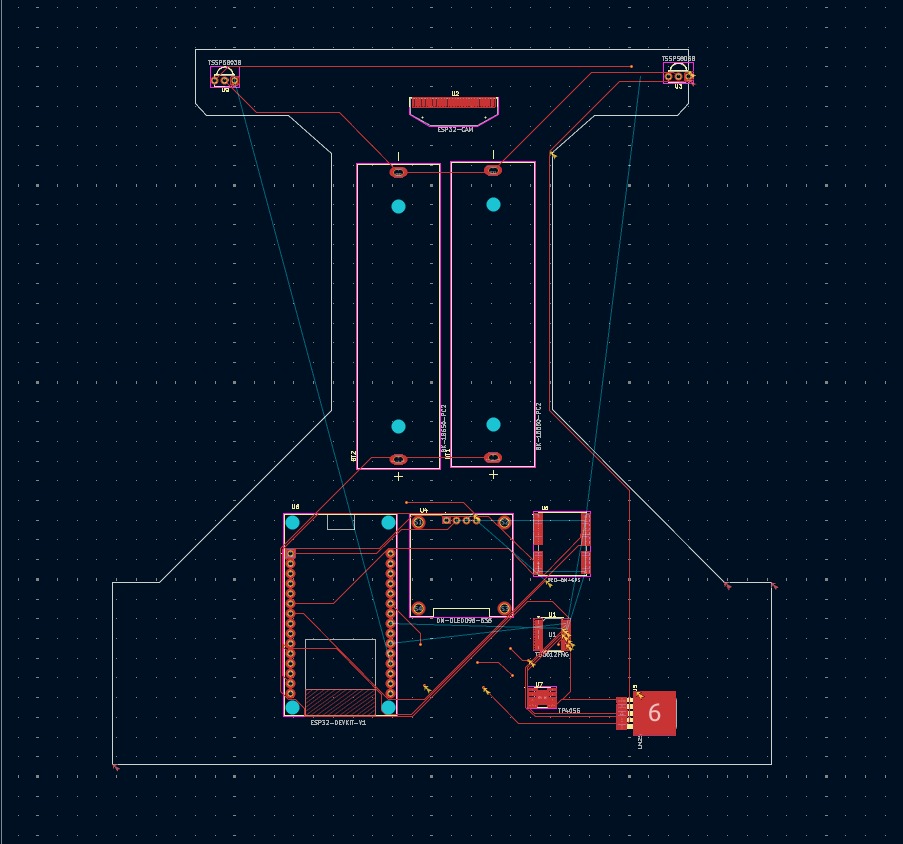 |
VM pin, keeping motor noise and current surges off the microcontroller supply rail.📖 Full Details: For layer stackups, see PCB Design. For power tree analysis, see Power System Documentation.
As part of the hackathon's "Brownie Points" challenge, a polarity-independent isolated flyback power supply was designed and simulated in LTSpice.
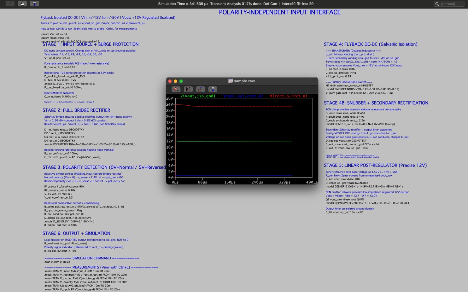
[!NOTE] Source Disclosure: The original hackathon repository included the simulation output waveform and schematic notes as an image (
ltspice-flyback-output.jpeg). The standalone SPICE netlist files (polarity_protection_flyback.cirandpolarity_protection_flyback.net) were reconstructed from the complete netlist text preserved in that original simulation output, allowing the circuit to be opened and executed in standard SPICE simulators.
📖 Full Details: For stage-by-stage equations and netlists, see Simulation Documentation.
Electabuzz_Unplugged/
├── .gitignore                              # KiCad, LTSpice, CAD, and OS ignore rules
├── README.md                               # Project showcase and overview
│
├── docs/                                  # Technical documentation
│   ├── architecture.md                    # System block diagrams & pin assignments
│   ├── hardware.md                        # Component specifications & mounting
│   ├── pcb-design.md                      # KiCad layout, stackup & ERC/DRC details
│   ├── power-system.md                    # Power tree & domain separation analysis
│   ├── simulation.md                      # Simulation challenge summary
│   ├── bom/                               # Manufacturing Bill of Materials
│   │   ├── README.md                      # Verified component list
│   │   ├── Bill_of_Materials.docx         # Original DOCX BOM
│   │   └── BOM.pdf                        # Original PDF BOM
│   └── assets/images/                     # Design screenshots and renders
│
├── hardware/
│   ├── pcb/                               # KiCad 9.0 PCB project files
│   │   ├── team_electrabuzz.kicad_pro     # Project master file
│   │   ├── team_electrabuzz.kicad_sch     # System schematic
│   │   └── team_electrabuzz.kicad_pcb     # PCB layout
│   └── cad/models/                        # 3D mechanical STEP models
│       ├── BK-18650-PC2--3DModel-STEP-269445.STEP
│ ├── DM-OLED096-636--3DModel-STEP-56544.STEPgit clone https://github.com/MayankBagad/Electabuzz_Unplugged.githardware/pcb/team_electrabuzz.kicad_pro in KiCad.simulation/polarity_protection_flyback.cir..tran 0 20m 0 1u uic).[!NOTE] An open-source license has not yet been selected for this repository. Recommended options:
- Hardware Designs: CERN-OHL-P-2.0 (Permissive) or CC-BY-SA-4.0
- Software / Netlists: MIT License or Apache-2.0
| Qty | Value | Footprint | References |
|---|---|---|---|
| 2 | BK-18650-PC2 | BK-18650-PC2:BAT_BK-18650-PC2 | BT1, BT2 |
| 2 | TSSP58038 | OptoDevice:Vishay_MINICAST-3Pin | U3, U9 |
| 1 | DM-OLED096-636 | DM-OLED096-636:MODULE_DM-OLED096-636 | U4 |
| 1 | ESP32-CAM | Display:OLED-128O064D | U2 |
| 1 | ESP32-DEVKIT-V1 | ESP32-DEVKIT-V1:MODULE_ESP32_DEVKIT_V1 | U8 |
| 1 | LM2596 | LM2596:TO263-5 | U5 |
| 1 | NEO-6M-GPS | NEO-6M-GPS:XCVR_NEO-6M-GPS | U6 |
| 1 | TB6612FNG | Package_SO:SSOP-24_5.3x8.2mm_P0.65mm | U1 |
| 1 | TP4056 | TP4056 symbol and footprint:SOP127P600X175-9N | U7 |
It measures 167.1 × 181.2 mm and has 2 copper layers, 1.6 mm thick.
11 parts, built around the ESP32-CAM, LM2596S-5.0, TSSP58038 and TP4056. The full list of its parts is on this page, with links to each part's symbol and footprint where PCBKit's library has them.
From the MayankBagad/Electabuzz_Unplugged repository on GitHub, at the commit this page was made from: the board is hardware/pcb/team_electrabuzz.kicad_pcb and its schematic hardware/pcb/team_electrabuzz.kicad_sch. PCBKit opens the board in the browser, with nothing to install.
Its repository states no licence, so its author keeps all rights: ask MayankBagad before reusing the design.
Circuit-Digest/ESP32-Cam-Surveillance-Car
Watch full video on ESP32 surveillance car


z-XOF-z/FT150TS
Tablero digital + launcher para Android que funciona solo con el teléfono del manubrio y está listo para una tarjeta ESP32 en la moto.

dotcypress/ir-smart-led-controller
IR Remote Controller for WS2812(or analog) LED Strip

XasWorks/dragon-home
A rework of our old SmartHome project, this time done cleanly and neatly~