
4 layers96 × 100 mm
OtterCastAmp
Ottercast/OtterCastAmp
OtterCastAmp is an open-source WiFi Speaker amplifier, based on a Sochip S3 SoC. Powered by any USB PD adapter for up to 100W of music.
272 parts341MIT

 maxses/hw-ophio
USB to UART adapter board (KiCad)
Ophio is an open-source printed circuit board by maxses, from the maxses/hw-ophio repository on GitHub. It is a 2-layer board of 33 × 20.3 mm with 36 parts on 30 nets, routed with 374 tracks and 39 vias.
It is built around the MIC5501-3.0YM5-TR. Its parts include 12 resistors, 7 capacitors, 5 diodes, 4 connectors and 2 ICs. It belongs with the interfaces and adapters boards and the STM32 boards of this library.
| Name | Ophio |
| URL | Link |
| HW-Rev | v0.1.x |
| Docu | 20220808 |
| IC | MCP2221 |
Ophio is an USB to UART adapter. It has an Micro-USB connector to be connected to a host computer and an 2,54mm pin socket.
Additional to the pin socket the PCB has an 10 Pin FPC interface for campo devices (STM32 boards).
The device also provides an I2C-Bus via USB. An extern 3V LDO (referring to the MCP2221) is used. The I2C runs on 3V.
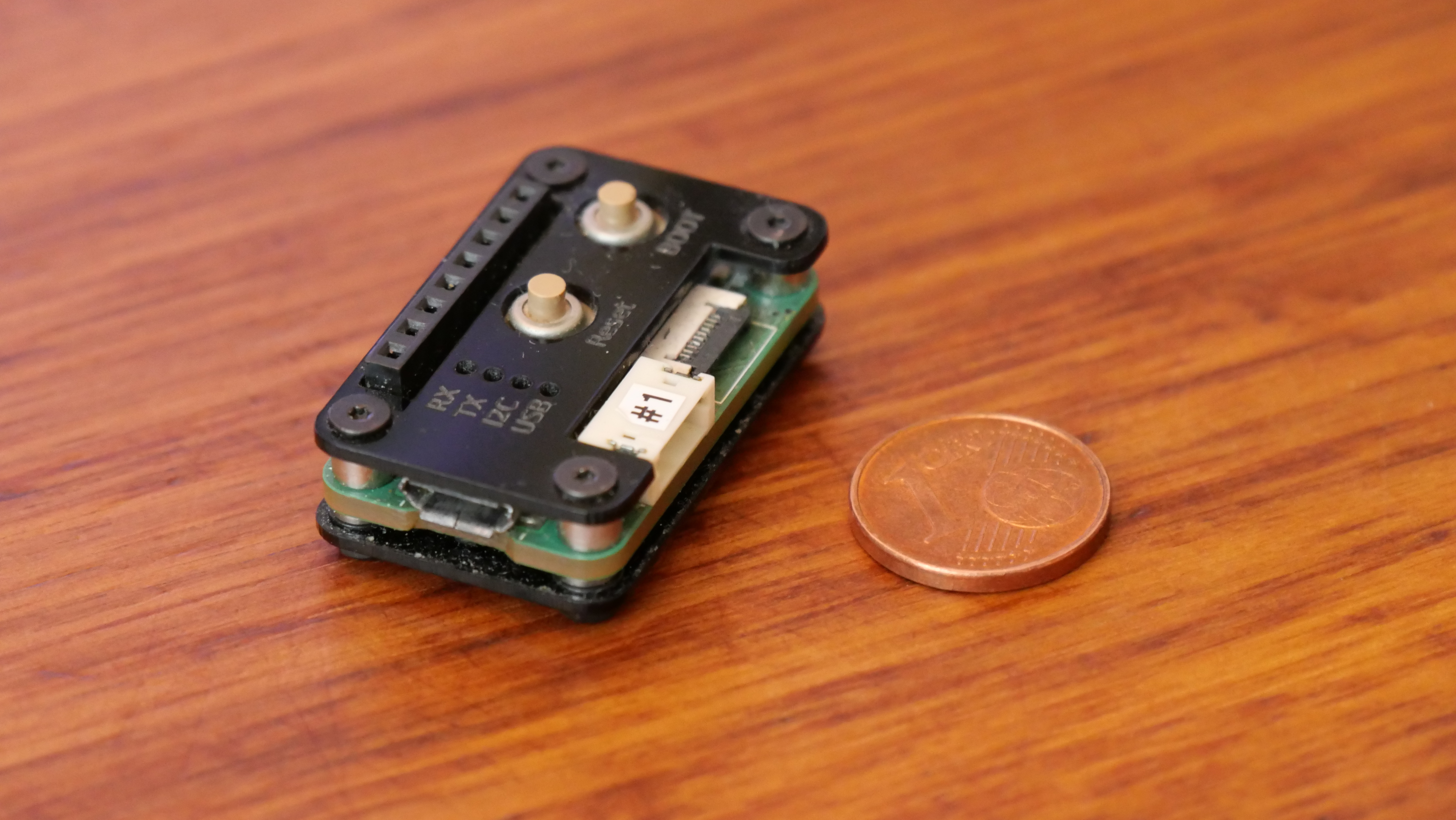
| Top | Bottom |
|---|---|
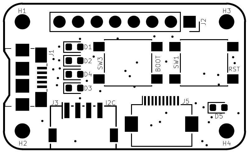 | 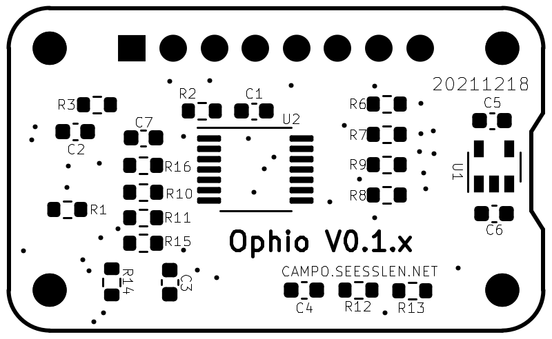 |
| Connector-pin | IC-/Board-Pin | Function |
|---|---|---|
| 1 | VDD | VDD Target |
| 2 | - | SWCLK |
| 3 | GND | GND |
| 4 | - | SWDIO |
| 5 | SW3 | NRST |
| 6 | - | NC (Reserved for SWO) |
| 7 | #5 URx | UART TX(TAGET) |
| 8 | #6 UTx | UART RX(TAGET) |
| 9 | VUSB | VIN 5V |
| 10 | SW1 | BOOT0 |
| Connector-pin | IC-/Board-Pin | Function |
|---|---|---|
| 1 | - | GND |
| 2 | VDD | VDD Ophio, 3V |
| 3 | - | VDD Target |
| 4 | - | VUSB |
| 5 | 5 URx | RX (PC) |
| 6 | 6 UTx | TX (PC) |
| 7 | 10 SCL | I2C SCL |
| 8 | 9 SDA | I2C SDA |
| Connector-pin | IC-/Board-Pin | Function |
|---|---|---|
| 1 | - | GND |
| 2 | VDD | VDD Ophio, 3V |
| 3 | 10 SCL | I2C SCL |
| 4 | 9 SDA | I2C SDA |
| Component | IC-/Board-Pin | Function |
|---|---|---|
| LED D1 Green | 2 GP0 | Uart RX (PC) |
| LED D2 Red | 3 GP1 | Uart TX (PC) |
| LED D3 Amb | 7 GP2 | USB device config |
| LED D4 Yel | 8 GP3 | I2C Traffic |
The STM32-Flasher tool can be used to flash targets. Its available on the website of ST. Following procedure has to be performed to start target devices in internal booloader mode.
After bringing the device into internal bootloader mode, the tool can be used to flash specific firmware. e.g.:
stm32flash -w miniminutnik_3.0.0.bin /dev/ttyACM0Note: for STM32L0 devices (e.g. miniminutnik) at least stm32flash 0.6.0 is needed Note: some target devices don't have routed the BOOT-Pin to the FPC-connector (e.g. miniminutnik). You need to press the according boot-button on the target instead of on ophio.
On linux systems "minicom" can be used to access the target device.
minicom -D /dev/ttyACM0 --color=on| Qty | Value | Footprint | References |
|---|---|---|---|
| 5 | 560 | Resistor_SMD:R_0603_1608Metric | R6, R7, R8, R9, R14 |
| 4 | MountingHole | MountingHole:MountingHole_2.1mm | H1, H2, H3, H4 |
| 3 | 100n | Capacitor_SMD:C_0603_1608Metric | C1, C2, C4 |
| 2 | 10K | Resistor_SMD:R_0603_1608Metric | R4, R5 |
| 2 | 1µ | Capacitor_SMD:C_0603_1608Metric | C5, C6 |
| 2 | LED_GRN | LED_SMD:LED_0603_1608Metric | D1, D5 |
| 1 | 0 | Resistor_SMD:R_0603_1608Metric | R12 |
| 1 | 0_OP | Resistor_SMD:R_0603_1608Metric | R13 |
| 1 | 100nF | Capacitor_SMD:C_0603_1608Metric | C3 |
| 1 | 10M | Resistor_SMD:R_0603_1608Metric | R3 |
| 1 | 10k | Resistor_SMD:R_0603_1608Metric | R2 |
| 1 | 10n | Capacitor_SMD:C_0603_1608Metric | C7 |
| 1 | 680 | Resistor_SMD:R_0603_1608Metric | R1 |
| 1 | BOOT | Button_Switch_SMD:SW_Push_1P1T_NO_6x6mm_H9.5mm | SW1 |
| 1 | DBG | Connector_FFC-FPC:Hirose_FH12-10S-0.5SH_1x10-1MP_P0.50mm_Horizontal | J5 |
| 1 | I2C | footprints:Connector_ZH_CONN_S4B-ZR-SM4A-TF | J3 |
| 1 | I8 | Connector_PinSocket_2.54mm:PinSocket_1x08_P2.54mm_Vertical | J2 |
| 1 | LED_AMB | LED_SMD:LED_0603_1608Metric | D3 |
| 1 | LED_RED | LED_SMD:LED_0603_1608Metric | D2 |
| 1 | LED_YEL | LED_SMD:LED_0603_1608Metric | D4 |
| 1 | MCP2221AxST | Package_SO:TSSOP-14_4.4x5mm_P0.65mm | U2 |
| 1 | MIC5501-3.0YM5 | Package_TO_SOT_SMD:SOT-23-5 | U1 |
| 1 | Reset | Button_Switch_SMD:SW_Push_1P1T_NO_6x6mm_H9.5mm | SW3 |
| 1 | USB_B_Micro_copy | digikey-footprints:USB_Micro_B_Female_10118192 | J1 |
Ottercast/OtterCastAmp
OtterCastAmp is an open-source WiFi Speaker amplifier, based on a Sochip S3 SoC. Powered by any USB PD adapter for up to 100W of music.

dartcom/ssd2828-dev
A carrier board for the ssd2828 and the LH154Q01 & VS035ZSM lcd panels


great-houk/mx_master_remake
[probe-rs]: https://crates.io/crates/probe-rs [defmt]: https://github.com/knurling-rs/defmt [flip-link]: https://github.com/knurling-rs/flip-link


It measures 33 × 20.3 mm and has 2 copper layers, 1.6 mm thick.
36 parts, built around the MIC5501-3.0YM5-TR. The full list of its parts is on this page, with links to each part's symbol and footprint where PCBKit's library has them.
From the maxses/hw-ophio repository on GitHub, at the commit this page was made from: the board is kicad/ophio.kicad_pcb and its schematic kicad/debug.kicad_sch. PCBKit opens the board in the browser, with nothing to install.
Its repository states no licence, so its author keeps all rights: ask maxses before reusing the design.